Download
1 / 30
300 likes | 551 Views
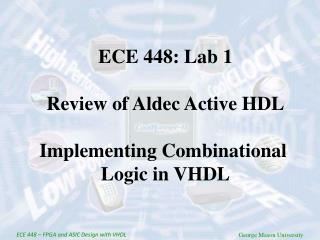
ECE 448: Lab 1 Review of Aldec Active HDL Implementing Combinational Logic in VHDL. ECE 44 8 – FPGA and ASIC Design with VHDL. George Mason University. Part 1. Introduction to Aldec Active-HDL. Example: MLU. MLU Block Diagram. MUX_0. 0 1. 0 1. 0 1. A1. A. MUX_4_1. Y1. IN0.

E N D
ECE 448: Lab 1 Review of Aldec Active HDL Implementing Combinational Logic in VHDL ECE 448 – FPGA and ASIC Design with VHDL George Mason University
Part 1 Introduction to Aldec Active-HDL Example: MLU
MLU Block Diagram MUX_0 0 1 0 1 0 1 A1 A MUX_4_1 Y1 IN0 MUX_1 NEG_A IN1 MUX_2 Y OUTPUT IN2 SEL0 IN3 SEL1 NEG_Y B1 B L1 L0 MUX_3 NEG_B
Experiment 1 Problem 1 ALU of PicoBlaze
Register File of PicoBlaze 8-bit Address s0 s1 s2 s3 s4 s5 s6 s7 0 7 0 1 0 7 2 7 0 3 7 0 4 7 0 5 7 0 16 Registers 7 0 6 7 0 7 sF F 7 0
Condition Code Registers (Flags) and its Definition Flags are set or reset after ALU operations Zero flag - Z zero condition Z = 1 if result = 0 0 otherwise Carry flag - C overflow, underflow, or various conditions Example* C = 1 if result > 28-1 or result < 0 0 otherwise *Applies only to addition or subtraction related instructions, refer to following slides otherwise
Syntax and Terminology Syntax Example Definition sX kk PORT(kk) PORT((sX)) RAM(kk) s15 14 PORT(2) PORT((S10)) RAM(4) Value at register 15 Value 14 Input value from port 2 Input value from port specified by register 10 Value from RAM location 4
Addressing modes Immediate mode s2 + 15 + C s2 s7 – 7 s7 ADDCY s2, 15 SUB s7, 7 Direct mode PORT(28) s10 s10 + s15 s10 INPUT s10, 28 ADD s10, s15 Indirect mode PORT((s2)) s9 s3 RAM((s10)) INPUT s9, s2 STORE s3, s10
Assembly language vs. machine code Assembly language mnemonic [operands] ADDCY s2, 16 SUB s7, s8 Machine code* opcode [operands] instruction 1A 2, 10 1A210 1C 7, 8 1C780 *Value in HEX
Logic instructions C Z • AND • AND sX, sY • sX & sY => sX • AND sX, kk • sX & kk => sX • 2. OR • OR sX, sY • sX & sY => sX • OR sX, kk • sX & kk => sX • 3. XOR • XOR sX, sY • sX & sY => sX • XOR sX, kk • sX & kk => sX IMM, DIR IMM, DIR IMM, DIR
Arithmetic Instructions C Z • Addition • 1.1 ADD sX, sY • sX + sY => sX • ADD sX, kk • sX + kk => sX • 1.2 ADDCY sX, sY • sX + sY + CARRY => sX • ADDCY sX, kk • sX + kk + CARRY => sX • 2. Subtraction • 2.1 SUB sX, sY • sX - sY => sX • SUB sX, kk • sX - kk => sX • 2.2 SUBCY sX, sY • sX - sY - CARRY => sX • SUBCY sX, kk • sX - kk - CARRY => sX IMM, DIR IMM, DIR
Test and Compare Instructions C Z TEST TEST sX, sY sX & sY => none TEST sX, kk sX & kk => none COMPARE COMPARE sX, sY sX – sY => none COMPARE sX, kk sX – kk => none IMM, DIR IMM, DIR
Data Movement Instructions (1) C Z - - LOAD LOAD sX, sY sY => sX LOAD sX, kk kk => sX STORE STORE sX, PP sX => RAM(PP) STORE sX, (sY) sX => RAM((sY)) FETCH FETCH sX, PP RAM(PP) => sX FETCH sX, (sY) RAM((sY)) => sX IMM, DIR - - DIR, IND - - DIR, IND
Data Movement Instructions (2) C Z - - INPUT INPUT sX, PP sY => PORT(PP) INPUT sX, (sY) sX => PORT((sY)) OUTPUT OUTPUT sX, PP PORT(PP) => sX OUTPUT sX, (sY) PORT((sY)) => sX DIR, IND - - DIR, IND
Edit instructions - Shifts *All shift instructions affect Zero and Carry flags
Edit instructions - Rotations *All rotate instructions affect Zero and Carry flags
Part 2 Mini ALU
opcode 4 4 A 4 Mini ALU 4 R B 4 M
Example 3 Variable Rotator
Function C = A <<< B A – 4-bit data input B – 2-bit rotation amount
Interface A 4 2 B 4 C
A(1) A(0) Fixed Shifts in VHDL A>>1 A(3) A(2) ‘0’ ‘0’ A(3) A(2) A(1) A_shiftR <= ‘0’ & A(3 downto 1);
Arithmetic Functions in VHDL (1) To use arithmetic operations involving std_logic_vectors you need to include the following library packages: library ieee; use ieee.std_logic_1164.all; use ieee.STD_LOGIC_UNSIGNED.ALL;
Arithmetic Functions in VHDL (2) You can use standard +, - operators to perform addition and subtraction: signal A : STD_LOGIC_VECTOR(3 downto 0); signal B : STD_LOGIC_VECTOR(3 downto 0); signal C : STD_LOGIC_VECTOR(3 downto 0); …… C<= A + B;