Download

1 / 36
420 likes | 944 Views
ME 350 – Lecture 5 – Chapters 23 & 24. Ch 23 - CUTTING TOOL TECHNOLOGY Ch 24 - ECONOMIC AND PRODUCT DESIGN CONSIDERATIONS IN MACHINING. Three Modes of Tool Failure. Cutting force is excessive and/or dynamic, leading to brittle fracture:

E N D
ME 350 – Lecture 5 – Chapters 23 & 24 • Ch 23 - CUTTING TOOL TECHNOLOGY • Ch 24 - ECONOMIC AND PRODUCT DESIGN CONSIDERATIONS IN MACHINING
Three Modes of Tool Failure • Cutting force is excessive and/or dynamic, leading to brittle fracture: • Cutting temperature is too high for the tool material: • Preferred wearing of the cutting tool:
Preferred Mode: • Longest possible tool life, wear locations: • Crater wear location: • Flank wear location:
Tool Wear vs. Time Tool wear as a function of cutting time. Flank wear (FW) is used here as the measure of tool wear. Crater wear follows a similar growth curve.
Effect of Cutting Speed Effect of cutting speed on tool flank wear (FW) for three cutting speeds, using a tool life criterion of 0.50 mm flank wear.
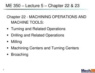
Tool Life vs. Cutting Speed Log‑log plot of cutting speed vs tool life.
Taylor Tool Life Equation • where v = cutting speed; • T = tool life; and • n and C are parameters that depend on feed, depth of cut, work material, and tooling material, but mostly on material (work and tool). • n is the • C is the on the speed axis at one minute tool life
Tool Near End of Life • Changes in sound emitted from operation • Chips become ribbon-like, stringy, and difficult to dispose of • Degradation of surface finish • Increased power required to cut Visual inspection of the cutting edge with magnifying optics can determine if tool should be replaced
Desired Tool Properties • Toughness ‑ to avoid fracture failure • Hot hardness ‑ ability to retain hardness at high temperatures • Wear resistance ‑ hardness is the most important property to resist abrasive wear
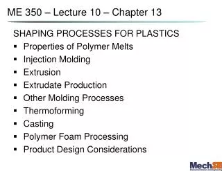
Hot Hardness Plain carbon steel shows a rapid loss of hardness as temperature increases. High speed steel is substantially better, while cemented carbides and ceramics are significantly harder at elevated temperatures.
Coated Carbide Tool Photomicrograph of cross section of multiple coatings on cemented carbide tool (photo courtesy of Kennametal Inc.)
Typical Values of n and C Tool materialnC (m/min)C (ft/min) High speed steel: Non-steel work 0.125 120 350 Steel work 0.125 70 200 Cemented carbide Non-steel work 0.25 900 2700 Steel work 0.25 500 1500 Ceramic Steel work 0.6 3000 10,000
Tool Geometry Two categories: • Single point tools • Used for turning, boring, shaping, and planing • Multiple cutting edge tools • Used for drilling, reaming, tapping, milling, broaching, and sawing
Single-Point Tool Geometry (a) Seven elements of single‑point tool geometry; and (b) the tool signature convention that defines the seven elements.
Holding the Tool Three ways of holding and presenting the cutting edge for a single‑point tool: (a) solid tool (typically HSS); (b) brazed cemented carbide insert, and (c) mechanically clamped insert, used for cemented carbides, ceramics, and other very hard tool materials.
Common Insert Shapes Common insert shapes: (a) round, (b) square, (c) rhombus with two 80° point angles, (d) hexagon with three 80° point angles, (e) triangle (equilateral), (f) rhombus with two 55° point angles, (g) rhombus with two 35° point angles.
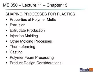
Twist Drills • The most common cutting tool for hole‑making • Usually made of high speed steel Standard geometry of a twist drill.
Twist Drill Issues • Along radius of cutting edges cutting speed: • Relative velocity at drill point is , (no cutting takes place) a large thrust force must deform the material • Problems: • Flutes must provide sufficient clearance to allow chips to be extracted: • Rubbing between outside diameter of drill bit and hole. Delivery of cutting fluid to drill point is difficult because chips are flowing in opposite direction:
Cutting Fluids (Lubricants and Coolants) Function is to improve cutting performance: • Improvechip • Reduce • Improve surface Types of cutting fluids: • Generally water based: – more effective at cutting speeds that are: • Generally oil based: – more effective at cutting speeds that are:
Machinability Criteria in Production • Tool life – longer tool life for the given work material means better machinability • Forces and power – lower forces and power mean better machinability • Surface finish – better finish means better machinability • Ease of chip disposal – easier chip disposal means better machinability
Tolerances and Surface Finish • Tolerances • Machining provides high accuracy relative to most other shape-making processes • Closer tolerances usually mean higher costs • Surface roughness in machining determined by: • Geometric factors of the operation • Work material factors • Vibration and machine tool factors
Effect of Cutting Conditions: End Cutting Nose Radius Feed Edge Angle
Ideal Surface Roughness where Ri = theoretical arithmetic average surface roughness; f = feed; NR = nose radius
Work Material Factors • Built‑up edge effects • Damage to surface caused by chip • Tearing of surface when machining ductile materials • Cracks in surface when machining brittle materials • Friction between tool flank and new work surface
Effect of Work Material Factors To predict actual surface roughness, first compute ideal surface roughness, then multiply by the ratio from the graph
Vibration and Machine Tool Factors • Related to machine tool, tooling, and setup: • Chatter (vibration) in machine tool or cutting tool • Deflections of fixtures • Backlash in feed mechanism • If chatter can be eliminated, then surface roughness is determined by geometric and work material factors
How To Avoid Chatter • Add stiffness and/or damping to setup • Operate at speeds that avoid frequencies close to natural frequency of machine tool system • Reduce feed (and sometimes depth) • Change cutter design • Use a cutting fluid
Determining Feed • Select feed first, speed second • Determining feed rate depends on: • Tooling – harder tool materials require lower feeds • Is the operations roughing or finishing? • Constraints on feed in roughing • Limits imposed by forces, setup rigidity, and sometimes horsepower • Surface finish requirements in finishing • Select feed to produce desired finish
Optimizing Cutting Speed • Select speed to achieve a balance between high metal removal rate and suitably long tool life • Mathematical formulas available to determine optimal speed • Two alternative objectives in these formulas: • Maximum • Minimum
Maximum Production Rate • Maximizing production rate = minimizing cutting time per unit • In turning, total production cycle time for one part consists of: • Part handling time per part = Th • Machining time per part = Tm • Tool change time per part = Tt/np, where np = number of pieces cut in one tool life (round down) • Total time per unit product for operation: Tc = Th + Tm + Tt/np
Minimizing Cost per Unit • Inturning, total production cycle cost for one part consists of: • Cost of part handling time = CoTh , where Co = cost rate for operator and machine • Cost of machining time = CoTm • Cost of tool change time = CoTt/np • Tooling cost = Ct/np , where Ct = cost per cutting edge • Total cost per unit product for operation: Cc = CoTh + CoTm + CoTt/np + Ct/np
Comments on Machining Economics • As C and n increase in Taylor tool life equation, optimum cutting speed • Cemented carbides and ceramic tools, compared to HSS, should be used at speeds: • vmax is always greater than vmin • Reason: Ct/np term in unit cost equation pushes optimum speed to left in the plot • As tool change time Tt and/or tooling cost Ct increase, cutting speed should be reduced • Disposable inserts have an advantage over regrindable tools if tool change time is significant
Product Design Guidelines • Design parts that need no machining • Use netshape processes such as precision casting, closed die forging, or plastic molding • If not possible, then minimize amount of machining required • Use near net shape processes such as impression die forging
Product Design Guidelines • Machined features such as sharp corners, edges, and points should be avoided • They are difficult to machine • Sharp internal corners require pointed cutting tools that tend to break during machining • Sharp corners and edges tend to create burrs and are dangerous to handle