Download
1 / 34
390 likes | 781 Views
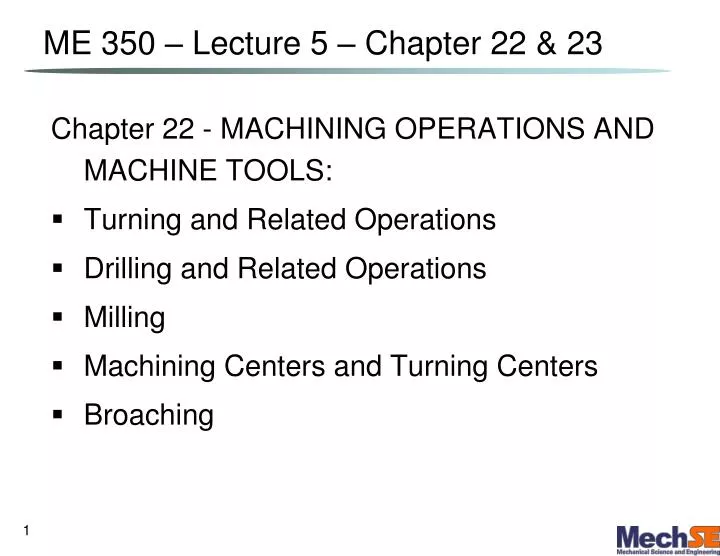
ME 350 – Lecture 5 – Chapter 22 & 23. Chapter 22 - MACHINING OPERATIONS AND MACHINE TOOLS: Turning and Related Operations Drilling and Related Operations Milling Machining Centers and Turning Centers Broaching. Turning.

E N D
ME 350 – Lecture 5 – Chapter 22 & 23 Chapter 22 - MACHINING OPERATIONS AND MACHINE TOOLS: • Turning and Related Operations • Drilling and Related Operations • Milling • Machining Centers and Turning Centers • Broaching
Turning Single point cutting tool removes material from a rotating workpiece to generate a cylinder • Performed on a machine tool called a: • Variations of turning performed on a lathe: • Facing • Contour turning • Chamfering • Cutoff • Threading
Chamfering Cutoff Cutting edge cuts an angle on the corner of the cylinder, forming a "chamfer" Tool is fed radially into rotating work at some location to cut off end of part
Threading Contour Turning Facing Tool follows a contour that is other than straight Tool is fed radially Pointed form tool is fed at a large feed rate, thus creating threads
Turret Lathe Tailstock replaced by “turret” that holds up to six tools • Tools rapidly brought into action by indexing the turret • Tool post replaced by four‑sided turret to index four tools • Applications: high production work that requires a sequence of cuts on the part
Multiple Spindle Bar Machines • More than one spindle, so multiple parts machined simultaneously by multiple tools. Example: After each machining cycle, spindles (including collets and workbars) are indexed (rotated) to next position
Boring • Difference between boring and turning: • Boring is performed on the _________ diameter of an existing hole • Turning is performed on the _________ diameter of an existing cylinder • Boring machines • Horizontal or vertical - refers to the orientation of the machine spindle’s:
Reaming Tapping • Slightly enlarges a hole • Provides better: • Improves: Used to provide internal screw threads on an existing hole. Tool called a:
Radial Drill Large drill press designed for large parts
Milling Machining operation in which work is fed past a rotating tool with multiple cutting edges • Axis of tool rotation is perpendicular to feed • Two forms: (a) (b)
Slab Milling Slotting Basic form of peripheral milling in which the cutter width extends beyond the workpiece on both sides Width of cutter is less than workpiece width, creating a slot in the work
Face Milling End Milling Profile Milling Cutter overhangs work on both sides Cutter diameter is less than work width, so a slot is cut into part Form of end milling in which the outside periphery of a flat part is cut
Machining Centers Highly automated machine tool can perform multiple machining operations under CNC control in one setup with minimal human attention • Typical operations are: • Other features: • Automatic tool changing • Pallet shuttles • Automatic workpart positioning
Mill-Turn Centers Highly automated machine tool that can perform the operations:
Broaching • Moves a multiple tooth cutting tool linearly relative to work in direction of tool axis Examples of internal broaching
Chapter 23: CUTTING TOOL TECHNOLOGY • Tool Life • Tool Geometry • Cutting Fluids
Three Modes of Tool Failure • Cutting force is excessive and/or dynamic, leading to brittle fracture: • Cutting temperature is too high for the tool material: • Preferred wearing of the cutting tool:
Preferred Mode: • Longest possible tool life, wear locations: • Crater wear location: • Flank wear location:
Tool Wear vs. Time Tool wear as a function of cutting time. Flank wear (FW) is used here as the measure of tool wear. Crater wear follows a similar growth curve.
Effect of Cutting Speed Effect of cutting speed on tool flank wear (FW) for three cutting speeds, using a tool life criterion of 0.50 mm flank wear.
Tool Life vs. Cutting Speed Log‑log plot of cutting speed vs tool life.
Taylor Tool Life Equation • where v = cutting speed; • T = tool life; and • n and C are parameters that depend on feed, depth of cut, work material, and tooling material, but mostly on material (work and tool). • n is the • C is the _______ on the speed axis at one minute tool life
Example Problem A tool run at 160m/min lasts for 5 min. If the tool is run at 100m/min it lasts for an average of 41 min. What is C and n?
Tool Near End of Life • Changes in sound emitted from operation • Chips become ribbon-like, stringy, and difficult to dispose of • Degradation of surface finish • Increased power required to cut Visual inspection of the cutting edge with magnifying optics can determine if tool should be replaced
Desired Tool Properties • Toughness ‑ to avoid fracture failure • Hot hardness ‑ ability to retain hardness at high temperatures • Wear resistance ‑ hardness is the most important property to resist abrasive wear
Hot Hardness Plain carbon steel shows a rapid loss of hardness as temperature increases. High speed steel is substantially better, while cemented carbides and ceramics are significantly harder at elevated temperatures.
Typical Values of n and C Tool materialnC (m/min)C (ft/min) High speed steel: Non-steel work 0.125 120 350 Steel work 0.125 70 200 Cemented carbide Non-steel work 0.25 900 2700 Steel work 0.25 500 1500 Ceramic Steel work 0.6 3000 10,000
Tool Geometry Two categories: • Single point tools • Used for turning, boring, shaping, and planing • Multiple cutting edge tools • Used for drilling, reaming, tapping, milling, broaching, and sawing
Single-Point Tool Geometry (a) Seven elements of single‑point tool geometry; and (b) the tool signature convention that defines the seven elements.
Holding the Tool Three ways of holding and presenting the cutting edge for a single‑point tool: (a) solid tool (typically HSS); (b) brazed cemented carbide insert, and (c) mechanically clamped insert, used for cemented carbides, ceramics, and other very hard tool materials.
Common Insert Shapes Common insert shapes: (a) round, (b) square, (c) rhombus with two 80 point angles, (d) hexagon with three 80 point angles, (e) triangle (equilateral), (f) rhombus with two 55 point angles, (g) rhombus with two 35 point angles.
Twist Drills • The most common cutting tool for hole‑making • Usually made of high speed steel Standard geometry of a twist drill.
Twist Drill Issues • Along radius of cutting edges cutting speed: • Relative velocity at drill point is _______, (no cutting takes place) a large thrust force must deform the material • Problems: • Flutes must provide sufficient clearance to allow chips to be extracted: • Rubbing between outside diameter of drill bit and hole. Delivery of cutting fluid to drill point is difficult because chips are flowing in opposite direction: