Download
1 / 20
200 likes | 318 Views
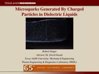
Discharges Between Charged Particles in Oil. Robert Geiger Advisor: Dr. David Staack Texas A&M University- Mechanical Engineering Plasma Engineering & Diagnostics Laboratory (PEDL). Outline. Motivation Liquid Discharges Particle Dynamics Single Charge Carrier Multiple Charge Carriers

E N D
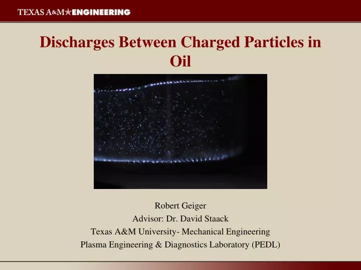
Discharges Between Charged Particles in Oil Robert Geiger Advisor: Dr. David Staack Texas A&M University- Mechanical Engineering Plasma Engineering & Diagnostics Laboratory (PEDL)
Outline • Motivation • Liquid Discharges • Particle Dynamics • Single Charge Carrier • Multiple Charge Carriers • Modes of Operation • Bubble • Microspark • Long Chain Spark • Chemistry • Summary
cells plasma wire Why Generate Plasma in Liquids? Chemical Applications: Water Sterilization Bio/Medical Fuel Reforming Physical Applications: Species Identification Microfluidics Shock Wave Generation Shock Wave
Discharge in Liquids - Process • Initiation Low Density Region • Electrolysis • Boiling (Joule Heating) • Electrostatic Cavitations • Breakdown • Primary Streamer • Secondary Streamer • Spark • Thermalization • Relaxation 1950s-1980s thoroughly studied breakdown process in dielectrics
Bubble Formation in Liquids • Making a Bubble is easy: Especially when you put 1 mJ in 8 μm3
Discharges in Liquids – Thermalization Spark Streamer Corona Anode (+) Cathode (-) < 50 um Water - Corona Mineral Oil - Corona
Low Energy Input – Double Spark Gap • Charcteristics • Energy Per Pulse ~ C • Stray Capacitance ~ 5 pF • Lowest Energy ~ 1 mJ R Spark Gap 1 Spark Gap 2 Output C V
Low Energy Input – Charge Carrier Method HV GND (V ~ 5 – 30 kV) ball Electrode • Spherical Capacitor • C = 4πε0R • R ~ 0.5 – 5 mm • C ~ 0.05 - 0.5 pF • E ~ 0.5 – 200 μJ 2R Discharge
Particle Dynamics – Contact Charging Field Enhancement Factor Lift off Voltage mg = qE g = qαV/d q = α CV α = (mgd/CV2)1/2 α ~ 1/β Experimental α ≈ 0.3 Charge relaxation τ = ε/σ For Mineral Oil ~ 0.5 s Liu, T. M.-C. (2010). The Design of a Micro/Nano-Particle Electrostatic Propulsion System.
HV Fel Fvis Particle Dynamics - Motion GND 1) Position 2) Velocity 3) Stokes Approximation , Mineral Oil Dielectric Strength: 200 kV/cm 4) Charge Relaxation 5) Electrical Breakdown Condition Ref. 1: Jones, Thomas B. Electromechanics of Particles. Cambridge University Press 1995 Ref. 2:Melcher, James R. Continuum Electromechanics. Cambridge, MA: MIT Press, 1981
Power Supply ICCD Experimental Setup – Single Charge Carrier Resistor Lens ICCD
Expermental • Light intensity decreases linearly with energy • Charge ~ pC • α ~ 0.3 (Same as before)
Multiple Charge Carrier - Batch Reactor • Voltage on electrodes transferred to charge carriers during contact. • Charge carriers move back and forth transferring charge. • Discharge power limited (~pC per discharge event). • Size, material, voltage control discharge parameters and chemistry.
4 s 6 s 12 s 14 s 20 s 0 s Discharge Modes: Multiple charge carriers 1) Gas Bubble Chain Formation • High temperature gas phase • DC Mode Glow Discharge • Duration ~ 5 s • Ballasted • Energy Determined by discharge current 2) Spark Chain Formation • High temperature liquid phase • Transient Spark • Energy determine by Capacitance • Duration ~ 10-100 ns 3) Microplasma Mode • Low temperature liquid phase • Power Density ~100 W/l
Summary • Control of plasma properties in liquids • Create non-thermal discharges in liquid • Interesting way to initiate nanosecond microsparks • Great control over discharge energy • Spark Gaps (mJ J) • Charge Carriers (uJ mJ ) • Scaling is possible • Cracking to lighter hydrocarbons Future Work • Self-organization of particles • Effect of energy per pulse on chemistry • Deforming charged particles
References Question? References: • Alyssa Wilson et al 2008 Plasma Sources Sci. Technol. 17 045001 • Ayato Kawashima et al, J. Appl. Phys. • D. Staack, A. Fridman, A. Gutsol et al., Angewandte Chemie-International Edition, vol. 47, no. 42, pp. 8020-8024, 2008. Acknowledgements: This material is based upon work suppoerted by the National Science Foundation Grant #1057175 PPPL for the use of High Speed Video Camera
Discharges in Liquids - Initiation Assumptions: All initiation mechanism achieve a low density reduction n Const (I) and (V) r Local Low Density Region (n) Boiling Analysis (Energy Balance) Electrolysis Analysis ( Faradays law of electrolysis) Y = (Yeild of Fluid) Electrostatic Cavitation Analysis (Force Balance) Cavitation Electrode Should be larger than Fluid