Download
1 / 79
790 likes | 906 Views
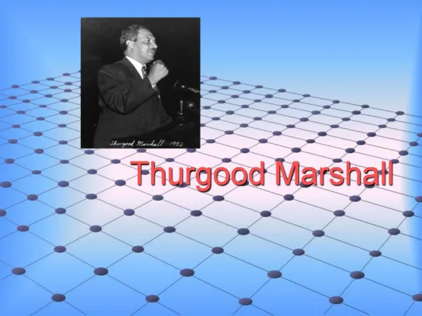
GIS in the Sciences ERTH 4750 (38031). Exploring and visualizing spatial data: Spatial structure, regional trends, local spatial dependence and anisotropy. Xiaogang (Marshall) Ma School of Science Rensselaer Polytechnic Institute Tuesday, Feb 19, 2013. Acknowledgements.

E N D
GIS in the Sciences ERTH 4750 (38031) Exploring and visualizing spatial data: Spatial structure, regional trends,local spatial dependence and anisotropy Xiaogang (Marshall) Ma School of Science Rensselaer Polytechnic Institute Tuesday, Feb 19, 2013
Acknowledgements • This lecture is partly based on: • Rossiter, D.G., 2012. Exploring and visualizing spatial data. Lecture in distance course Applied Geostatistics. ITC, University of Twente
Contents • Spatial structure: point distribution, postplots, quantile plots • Regional trends • Local spatial dependence: h-scatterplots, variogram cloud, experimental variogram • Anisotropy: variogram surfaces, directional variograms
1 Visualizing spatial structure • Distribution in space • Postplots • Quantile plots • Classified postplots
We begin by examining sets of sample points in space. • The first question is how these points are distributed over the space. Are they clustered, dispersed, in a regular or irregular pattern, evenly or un-evenly distributed over subregions? There are statistical techniques to answer these questions objectively; here we are concerned only with visualization.
1.1 Distribution in space • This is examined with a scatterplot on the coordinate axes, showing only the position of each sample. This can be in: • 1D : along a line or curve • 2D: in the plane or on a surface • 3D: in a volume of space • Note: We can not easily visualize higher dimensions, and they are not necessary for strictly geographic data.
Distribution plot of soil samples, Swiss Jura within a 1 x 1 km area
1.2 Postplots • These are the same as distribution plots, except they show the relative value of each point in its feature space by some graphic element: • relative size, or • color, or • both
Showing feature-space values with symbol size • One way to represent the value in feature space is by the symbol size, in some way proportional to the value. But, which size? • Radius proportional to value • Radius proportional to transformed value • Square root (because radius is 1D) • Logarithm to some base
Showing feature-space values with a color ramp • Another way to show the difference between feature-space values is with a color ramp, i.e. a sequence of colors from low to high values. • Different color ramps give very different impressions of the same data, as we now illustrate. • Warning: When points are widely-spaced, it is very difficult to pick out patterns shown by the color ramp, because the eye is confused by the background (no matter what color) where there are no points. The postplot using symbol size is usually a better choice. • Still, we show the color ramp here, so you can form your own opinion.
Showing feature-space values with sizes and a color ramp • And of course we can combine both visualization techniques in one graph.
1.3 Quantile plots • A quantile plot is a postplot where one quantile is represented in a contrasting size or color. This shows how that quantile is distributed. • A quantile is a defined range of the cumulativeempirical distribution of the variable. • The quantiles can be: • quartiles(0-25%, 25-50% . . . ); • deciles (0-10%, 10-20% . . . ); • any cutoff point interesting to the analyst, e.g. 95% (i.e. highest 5%)
Quantiles • Examples of quantiles of the Pb contents of 259 soil samples from the Swiss Jura: • Here are all the values, sorted ascending: • Here are some quantiles:
Quantile plot of Pb values (deciles), Swiss Jura Are any of the deciles concentrated in parts of the area? Are points in any or all of the deciles clustered?
1.4 Classified postplots • If the observations come from classes, it is possible to visualize these: • withoutthe values of some continuous attribute: just visualize where the different classes are located; • withthe values of some continuous attribute: also see if the continuous attribute depends on: • the class; • a regionaltrend; • a localspatial dependence; • or some combination.
Classified post-plot, with a continuous attribute What is the classifying attribute in this postplot? What is the continuous attribute in this postplot? Does the clay content appear to depend, at least to some extent, on the soil type?
2 Visualizing a regional trend • Origin of regional trends • Looking for a trend in the post-plot • Computing a trend surface
Regional trends • One kind of spatial structure is a regional trend, where the feature space value of the variable changes systematically with the geographic space coordinates. • A common example in many parts of the world is annual precipitation across a region, which decreases away from a source. • In a later lecture we will see how to combine a regional trend with local structure; here we just want to visualize any trend and assess it qualitatively.
2.1 Orders of trends • A systematic trend is an approximation to some mathematical surface; in a later lecture we will see how to find the mathematical representation. • For now, we are concerned with the formof the surface: • First-order, where the surface is a plane (also called linear): the attribute value changes by the same amount for a given change in distance away from an origin; • Second-order, where the surface is a paraboloid(2D version of a parabola), i.e. a bowl (lowest in the middle) or dome (highest in the middle) • Higher-order, where the surface has saddle points or folds
2.2 Looking for a trend in the post-plot • The post-plot shows localspatial dependence by the clusteringof similar attribute values. • It can also show a regional trend if the size or color of the symbols (related to the attribute values) systematically changeover the whole plot.
Post-plot showing a regional trend What is the regional pattern of the clay content shown in the previous graph? How much of the variability in clay content explained by the trend?
2.3 Visualizing a trend with a trend surface • From the set of points we can fit an empirical model which expresses the attribute as a function of the coordinates: • where is a coordinate vector, e.g. in 2D it might be: ) • Then we apply the fitted function over a regular grid of points, and display this as a map. Normally the points are represented as pixels. • We will see how to fit the surface in a later lecture; for now we visualize the results.
First-order Which of these two trend surfaces best fits the sample points? (Compare the overprinted post-plot with the surface) Is the second-order surface a bowl or dome? Second-order
3 Visualizing local spatial dependence • Point-pairs • h-scatterplots • Variogramclouds • Empirical variograms
We have seen in the postplots that there seems to be local spatial dependence. How can we visualize this? • The most common tool to evaluate local spatial dependence is the empirical variogram, which will be explained later. This is difficult for many people to understand when they first see this kind of graph. • So, we will begin with the concept of point-pairs and then see how we can relate point pairs at lag distances (to be defined). • Then the variogram should be easier to understand.
3.1 Point-pairs • Any two points are a point-pair. • If there are points in a dataset, there are (unique point-pairs; that is, any of the points can be compared to the other points. The Meuse data set has 155 sample points. How many point-pairs can be formed from these?
Comparing points in a point-pair • These can be compared in two ways: • Their locations, i.e. we can find the distanceand directionbetween them in geographicspace; • Their attribute values in feature space. • The combination of distanceand directionis called the separation vector.
Practical considerations for the separation vector • Except with gridded points, there are rarely many point-pairs with exactly the same separation vector. • Therefore, in practice we set up a bin, also called (for historical reasons) a lag, which is a rangeof distances and directions.
3.2 h-scatterplots • This is a scatterplot(i.e. two variables plotted against each other), with these two axes: • X-axisThe attribute value at a point; • Y-axisThe attribute value at a second point, at some defined distance (and possibly direction, to be discussed as anisotropy, below), from the first point. • All pairs of points (for short usually called point-pairs) separated by the defined distance are shown on the scatterplot.
Interpreting the h-scatterplot • If there is no relationbetween the values at the separation, the h-scatterplot will be a diffuse cloud with a low correlation coefficient. • If there is a strong relationbetween the values at the separation, the h-scatterplot will be close to the 1:1 line with a high correlation coefficient.
The next two slides show h-scatterplots for the Pb concentration in Jura soil samples at two resolutions: • Bins of 50 m (0.05 km) width up to 300 m (0.3 km) separation • Bins of 100 m (0.1 km) width up to 600 m (0.6 km) separation • Note that the x- and y-axes are in units of the attribute, in this case ppm Pb. • The 50 m bins only show the lower part of the Pb attribute value range (to 150 ppm Pb); the 100 m bins show the full attribute range (to about 300 ppm Pb).
The most common way to visualize local spatial dependence is the variogram, also called (for historical reasons) the semivariogram. • To understand this, we have to first define the semivarianceas a mathematical measure of the difference between the two points in a point-pair.
Semivariance (1) • This is a mathematical measure of the differencebetween the two points in a point-pair. It is expressed as squared difference so that the order of the points doesn't matter (i.e. subtraction in either direction gives the same results).
Semivariance (2) • Each pair of observation points has a semivariance, usually represented as the Greek letter (‘gamma’), and defined as: • where is a geographic point and is its attribute value. • (Note: The ‘semi’ refers to the factor , because there are two ways to compute for the same point pair.) • So, the semivariancebetween two points is half the squared differencebetween their values. If the values are similar, the semivariance will be small.
Here are the first two points of Jura soil sample dataset: • For this point-pair, compute: • The Euclidean distance between the points; • The differencebetween the Pb values; • The semivariancebetween the Pbvalues.
Now we know two things about a point-pair: • The distance between them in geographic space; • The semivariancebetween them in attribute space. • So… it seems natural to see if points that are ‘close by’ in geographical space are also ‘close by’ in attribute space. • This would be evidence of local spatial dependence.
3.3 The variogramcloud • This is a graph showing semivariances between all point-pairs: • X-axis The separation distance within the point-pair • Y-axis The semivariance • Advantage: Shows the comparison between all point-pairs as a function of their separation; • Advantage: Shows which point-pairs do not t the general pattern • Disadvantage: too many graph points, hard to interpret
Examples of a variogram cloud Left: separations to 2 km; Right: separations to 200 m • Can you see a trend in the semivariancesas the separation distance increases? • What is the difficulty with interpreting this graph?
Clearly, the variogram cloud gives too much information. If there is a relation between separation and semivariance, it is hard to see. The usual way to visualize this is by groupingthe point-pairs into lagsor binsaccording to some separation range, and computing some representative semivariancefor the entire lag. • Often this is the arithmetic average, but not always.
3.4 The empirical variogram • To summarize the variogram cloud, group the separations into lags (separation bins, like a histogram) • Then, compute the averagesemivariance of all the point-pairs in the bin • This is the empirical variogram
Empirical variogram • is the number of point pairs separated by vector h, in practice some range (bin) • These are indexed by ; the notation means the “tail” of point-pair , i.e., separated from the “head” by the separation vector . • Note: there are other ways to estimate the variogramfrom the variogram cloud; in particular so-called robust estimators.