Download
1 / 17
170 likes | 180 Views
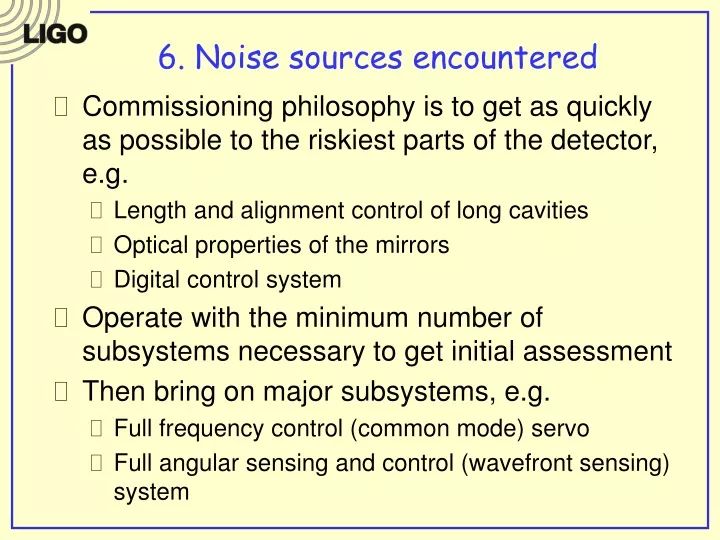
6. Noise sources encountered. Commissioning philosophy is to get as quickly as possible to the riskiest parts of the detector, e.g. Length and alignment control of long cavities Optical properties of the mirrors Digital control system

E N D
6. Noise sources encountered • Commissioning philosophy is to get as quickly as possible to the riskiest parts of the detector, e.g. • Length and alignment control of long cavities • Optical properties of the mirrors • Digital control system • Operate with the minimum number of subsystems necessary to get initial assessment • Then bring on major subsystems, e.g. • Full frequency control (common mode) servo • Full angular sensing and control (wavefront sensing) system
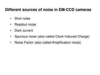
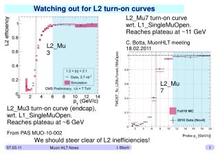
6. Noise sources encountered • Electronics noise • ADC noise analog whitening filters • DAC noise analog dewhitening filters • Sensing/dark noise detect more light • Digital suspensions and new coil drivers • Noisy analog electronics • RFI • Frequency noise • Common mode servo makes mode cleaner follow common arm as a quiet frequency reference • High bandwidth in three nested loops need 1 MHz bandwidth in PSL loop, 100 kHz bandwidth in MC loop, 20 kHz in CM loop • Hybrid digital-analog servo with blended actuation paths • Intensity noise • Sensing after mode cleaner added frequency noise • Dynamic range, saturations, non-linearities
6. Noise sources encountered • Acoustic noise and microphonics • Beam clipping on limiting apertures • Vibrational modes of periscopes • Phase noise on input light and at detection ports • Angular misalignments • 12 degrees of freedom need to be controlled to bring ifo to same DC operating point • Alignment sensitivity matrix depends on power in ifo (thermal lensing effects?) • Blend wavefront sensing and optical lever damping actuation paths • Auxiliary degrees of freedom • Sensing noise in Michelson (MICH) and power-recycling cavity (PRC) which sensed at a pick-off port with little light (low sensitivity) • Wedged optics in power-recycling cavity large coupling of 12 Hz bounce mode to longitudinal dof • High bandwidth with noisy sensor BAD news
Progression in Strain Sensitivity L1 S1 S2
3. Work Plan for Hanford after S3 • Optical noise (f 200 Hz) • Increase laser power • Thermal lensing • Thermal compensation • Increase RF sideband coupling into PRC • Increase overlap between Carrier and RF sideband at AS port • Acoustic mitigation (60 f few 100 Hz) • Complete REFL port work frequency noise • Auxilliary degrees of freedom (f 100 Hz) • Reduce sensing noise by detecting more light at POB • Damp vertical mode (at 12 Hz) to reduce bandwidth requirement of PRC and MICH loops • Engage correction paths (depends on stability of MICH AS coupling coefficient)
3. Work Plan for Hanford after S3 • Alignment control system (f 50 Hz) • Adaptive algorithms for ASC to include • Sideband power and arm power scalings • Radiation pressure compensation • RF phase • Wideband control loops to wean off optical lever • Beam centering to within 1mm on optics using zoom lenses and fast image processing
3. Work Plan for Hanford after S3 • Low noise DACs from FDI have 100x lower noise • New AS_I servo to subtract RF signal in “other” quadrature from photocurrent • Intensity stabilization • External pre-isolation (PEPI) • Wideband frequency servo boards • Output mode cleaner
7. Noise sources not aided by AdLIGO • AdLIGO is not an independent effort • Incorporate lessons of initial LIGO into AdLIGO design, and vice versa • Examples • Detection ports sensitivity to acoustics and microphonics enclose in vacuum in AdLIGO • Radiation pressure induced angular instability negative g-parameter arm cavities in AdLIGO • Seismic remediation at LLO AdLIGO hydraulic actuator • Correction of mirror figure at LHO AdLIGO thermal compensation system
14. Recent Graduates in LIGO/LSC And dozens of others …
14. Recent Graduates in LIGO/LSC And dozens of others, including engineering students, masters students, undergraduates …