Download

1 / 10
100 likes | 267 Views
Chapter 6 Low-Noise Design Methodology.

E N D
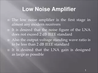
Low-noise design from the system designer’s viewpoint is concerned with the following problem: Given a sensor with known signal, noise, impedance, and response characteristics, how do we optimize the amplifier design to achieve the lowest value of equivalent input noise? • The answer is the amplifier portion of the system must be matched to the sensor. This matching is the essence of low-noise design. Circuit Design • When designing an amplifier for a specific application, there are many specifications to be met and decisions to be made. These include gain, bandwidth, impedance levels, feedback, stability, dc power, cost and signal-to-noise ratio requirements. Amplifier designers can elect one of 2 paths: • The wrong approach is to worry about the gain and bandwidth first and later in the design power they check for the noise. • Alternatively, one can design the system with initial emphasis on noise performance. • Although there are many low-noise devices available they do not perform equally for all signal sources.
To obtain the optimum noise performance , it is necessary to select the proper amplifying device (FET, BJT, or IC) and operating point for the specific sensor or input source. • Feedback and filtering can then be added to meet the additional design requirements Design Procedure • Select the input stage device, discrete or IC, BJT or FET • Select the operating point • If preliminary analysis shows that the noise specification can be met, a circuit configuration (CS, CG, CD) can be selected and the amplifier designed to meet the remainder of the circuit requirements • Noise is essentially unaffected by circuit configuration and overall negative feedback. Therefore the transistor and its operating point can be selected to meet the circuit noise requirements. • Then the configuration or feedback can be determined to meet the gain, bandwidth, and impedance requirements. • This approach allows the circuit designer to optimize for the noise and other circuits requirements independently.
After selecting a circuit configuration, analyzing it for non-noise requirements may indicate that it will not met all the specifications. If the bandwidth is too narrow, more stages and additional feedback can be added, the bias current of the input transistor can be increased or a transistor with a larger fT can be selected. The noise can be recalculated to see if it is still within specifications. This iterating process ensures obtaining satisfactory noise performance and prevents locking in on a high-noise condition at the very start of the design. • The ultimate limit of equivalent input noise is determined by the sensor impedance and the first stage, Q1, of the amplifier. • The source impedance Zs(f) and noise generators En(f) and In(f) representing Q1 are each a different function of frequency. Initial steps in the the design are the selection of the type of input device, such as BJT, FET or IC, and the associated operating point to obtain the desired noise characteristic as described above. • In the simplest case of a resistive source, match the amplifier’s optimum source resistance Ro to the resistance of the source of sensor. • If the amplifier is operated over a band of frequencies, the noise must be integrated over this interval.
By changing devices and/or operating points, theoretical performance can approach an optimum. • The noise of the first stage must be low to obtain overall low system noise. • The following stages cannot reduce noise no matter how good. • Subsequent stages can add noise so the design of these stages must be considered for a low-noise system. The usual problem is that there is not enough gain-bandwidth in the first stage to provide high gain with the bandwidth needed. Then the noise of the following stages may contribute. • After selecting the input stage the circuit is designed. Set up the biasing, determine the succeeding stages, the coupling networks and the power supply. • Then analyze the noise of the entire system, including the bias-network contributions to ensure that you can still meet the noise specifications. • Finally add the overall negative feedback to provide the desired impedance, gain and frequency response.
Optimum Source Resistance • The point at which the total equivalent input noise approaches closes to the thermal noise curve in the figure is significant • At this point the amplifier adds minimum noise to the thermal noise of the source. This optimum source resistance is called Ro and is defined as , where .
Selection of an Active Device • An active input device can be an IC with a bipolar or FET input stage or a discrete transistor. Selection depends primarily on the source impedance and frequency range. To assist in decisions in choosing the right active input devices, a general guide is shown below: • At the lowest values of source resistance, it is usually necessary to use transformer coupling at the input to match the source resistance to the amplifier Ro. Bipolar transistor s and bipolar input ICs are most useful at midrange impedances. Adjustment of Ro to match the source impedance is made by changing the transistor collector current with higher currents for lower Ro as given by
At higher values of source resistance, FETs are more desirable because of their very low noise current In. In some instances, they are even preferred when a low En is desired. • When operating with a very large range of source resistance such as in an instrumentation amplifier application, a JFET is generally preferred for the input stage. • A typical JFET has an En slightly larger than a BJT, but its In is significantly lower. • Another advantage of JFET is its higher input resistance and low input capacitance; thus it is particularly useful as a voltage amplifier. • For the highest source resistances the MOSFET with its extremely low In has an advantage. The MOSFET may have up to 10 to 100 times the 1/f voltage En of a JFET or BJT. As processing techiques have improved the MOSFETs are becoming more attractive as low noise devices. • The advantages of include low cost and compatibility with digital IC process. It is often desirable to combine a MOSFET input signal amplification stage with DSP on the the same chip.
IC amplifiers are usually the first choice for amplifier designs because of their low cost and ease of use. In selecting the one IC for your design, the source impedance and the transistor type must still be considered. All of the preceding statements about input stages apply when selecting the IC for your design. • For lower source impedances, select a bipolar unit IC and for higher impedances a FET input IC. • If state-of-the-art performance is need the use a discrete BJT or JFET stage ahead of the IC. Transformer Coupling • To couple the detector and amplifier in an electronic system, it is sometimes better to use a coupling or input transformer. When it is not possible to achieve the necessary noise figure using device selection, transformer coupling may be the solution. Very low resistance sources can cause this problem. • The use of an input transformer between the detector and amplifier improves the system noise performance by matching the sensor resistance with the amplifier’s optimum source resistance Ro.
Consider the secondary circuit as shown below that contains noise generators En and In. We have identified . When these quantities are reflected to the primary as En’ and In’ we obtain where T is the turn ratio.