Download
1 / 13
230 likes | 619 Views
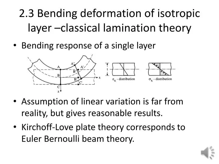
2.3 Bending deformation of isotropic layer –classical lamination theory. Bending response of a single layer Assumption of linear variation is far from reality, but gives reasonable results. Kirchoff -Love plate theory corresponds to Euler Bernoulli beam theory. Basic kinematics.

E N D
2.3 Bending deformation of isotropic layer –classical lamination theory • Bending response of a single layer • Assumption of linear variation is far from reality, but gives reasonable results. • Kirchoff-Love plate theory corresponds to Euler Bernoulli beam theory.
Basic kinematics • Normals to mid-plane remain normal • Bending strains proportional to curvatures
Hooke’s law • Moment resultants • D-matrix (EI per unit width)
Bending of symmetrically laminated layers • As in in-plane case, we add contributions of all the layers. • We still get M=D, but
The power of distance from mid-plane • In Example 2.21 we had a laminate made of brass and aluminum • For in-plane loads laminate was twice as close to aluminum than brass. • For bending, brass contribution proportional to . Aluminum contribution
Bending-extension coupling of unsymmetrical laminates • With unsymmetrical laminates, mid-plane is not neutral surface when only moment is applied. • Conversely pure bending deformation require both force and moment.
B-matrix • Force resultants needed to produce pure bending • How can we see that is B zero for symmetrical laminate? • Under both in-plane strains and curvatures
Under in-plane strains • In-plane strains require both force and moment • With similar derivation get • With both strains and curvatures +D
Example 2.3.1 • Two layer laminate aluminum on top (E=10Msi,G=3.7Msi, t=0.2”), brass under (E=15Msi, G=5.6Msi, t=0.05”). Bending moments applied, no in-plane loads leading to the following curvatures Calculate in-plane strains and bending moments. • We will outline textbook solution and check for reasonableness.
A Matrix • A=0.2Qal+0.05Qbr • Checks: • Ratios of diagonal terms. • Ratios of diagonals to off diagonals. • Diagonal terms approximately average moduli times total thickness (+10% correction due to Poisson’s ratio)
B-Matrix • Check: The B-matrix is due to offset distance between mid-plane and neutral plane. So it should be equal approximately to A matrix times the offset. On that basis the offset here is about 28,000/3.1e6=0.009”. Is this reasonable? • What other checks?
D-matrix • For all-aluminum • For all brass, 1.5 times larger. • Calculated D • Is it reasonable? • Other checks?
Strains • With no in-plane loads, strains should be the curvatures times the offset distance. • 1/in • Does it check?