Download
1 / 11
110 likes | 201 Views
Results of FEA for the PETS EBW tooling Riku Raatikainen 23.5.2011. Motivation for FEA: Demonstrating the structural behaviour of the PETS under compressive force in a workbench for welding

E N D
Results of FEA for the PETS EBW tooling RikuRaatikainen 23.5.2011
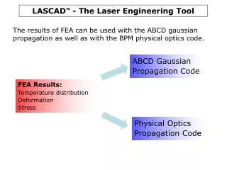
Motivation for FEA: • Demonstrating the structural behaviour of the PETS under compressive force in a workbench for welding • Before welding, the PETS structure is held together by a friction contact Appropriate force is needed, which holds the parts together in the workbench • Too large force values could lead into instability while smaller values are not capable of creating an appropriate friction contact
Assembly Inner Copper solid Outer Steel shell Couplers
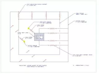
Workbench scheme Screw 1. Assembly and compression in a vertical position 2. Welding process in horizontal position
Sections Gaps (50 µm) for Welding
FE-Analysis • Assumptions and restrictions: • Maximum total deformation of 50 µm were allowed (transversal < 10-20 µm) • Friction factor between Copper-Copper surfaces roughly 1.0 • PETS under axial loading + the effect of gravity • The effect of rotational velocity was neglected since its small value (0.004 rad/s)
Mesh/Loads/Boundary Conditions The structure is supported from both ends, where the remote displacement (B) allows longitudinal movement. (total mass ≈45 kg)
Results Total deformation (µm), Loading case 1 kN Total deformation (µm), Loading case 300 N
Results Total deformation (µm), Loading case 10 kN Total deformation (µm), Loading case 5 kN
Results-Extra CLASH: Frictional contact fails, loading case 200 N. Overloading (def. > 50 µm), loading case 50 kN. Buckling Illustration of steel shell losing its stability if too large force value is applied.
Conclusion • The effect of gravity is seen significant (but still acceptable) in small force values below 1 kN and the total deformation is emphasized in vertical direction (due to gravity). Theoretical failing of the friction connection is at near 225 N • In loading cases where the force reaches 5 kN the longitudinal deformation emphasizes More stable structural behaviour in vertical direction • Axial loading cases of several tons will lead into instability • It should be noted that the FEM model did not include any safety factors and that the simulation model was approximately 10 kg lighter than the actual PETS structure In a reality the clashing is expected to occur around 300 N For reliable welding process a minimum clamping force of 1 kN should be considered as guiding value BUT • As seen the difference in deformation between the loading cases of 1 kN and 5 kN is only few micrometers! A clamping force of 5 kN is recommended to ensure a reliable friction contact and alignment during operations (transportation, manipulation etc.) • Exact forces can adjusted furthermore in machining • Parts to be welded could be attached into the structure by using spot welding before actual welding • Even more reliable and accurate alignment