Download
1 / 52
520 likes | 536 Views
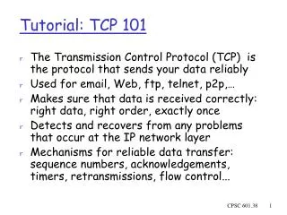
Learn about the sliding window mechanism used by TCP for flow control and window size issues in computer networks. Understand how to determine the Maximum Segment Size (MSS) and Path MTU.

E N D
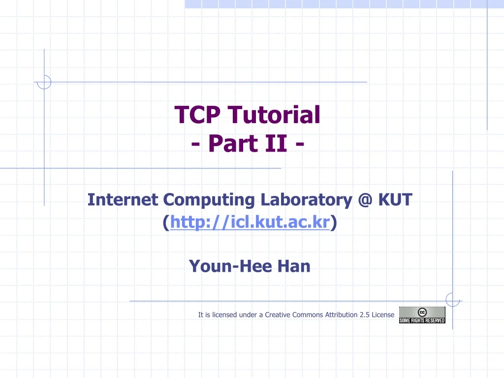
TCP Tutorial- Part II - Internet Computing Laboratory @ KUT (http://icl.kut.ac.kr) Youn-Hee Han It is licensed under a Creative Commons Attribution 2.5 License
Sliding Window Computer Network
Using Sliding Window:Transport Versus Data Link Layer • Potentially connects many different hosts • need explicit connection establishment and termination • Potentially different RTT • need adaptive timeout mechanism • Potentially long delay in network • need to be prepared for arrival of very old segments • Potentially different capacity at destination • need to accommodate different node capacity (flow-control) • Potentially different network capacity • need to be prepared for network congestion Computer Network
Sliding Window • Sliding Window Used By TCP • Measured in byte positions • Illustration • Bytes through 2 are acknowledged • Bytes 3 through 6 not yet acknowledged • Bytes 7 though 9 waiting to be sent • Bytes above 9 and lie outside the window cannot be sent • TCP sliding window mechanism operates at the octet (byte) level • TCP allows the window size to vary over time • Variable size window means thatTCP provides “flow control” Computer Network
Flow Control & TCP Window • Receiver controls flow by telling sender size of currently available buffer measured in bytes • Each acknowledgement contains a window advertisement that specifies how many additional bytes of data the receiver is prepared to accept. • The advertised window size represents the receiver’s current buffer size • Sender never sends more than the advertised window size • Receiver buffer will never overflow Computer Network
Flow Control & TCP Window Sender = client Receiver = server 0 Ack : 1001 , win : 4000 seq : 1001 , 4000 bytes 4000 Ack : 5001 , win : 0 2000 Ack : 5001 , win : 2000 seq : 5001 , 1000 bytes 3000 Computer Network
Window Size Issue See:http://icl.kut.ac.kr/2007_1/G_Course/tcp.shtml Default Window Size Computer Network
MSS (Maximum Segment Size) Computer Network
MSS (Maximum Segment Size) • Overview • Maximum Transmission Unit (MTU) is defined by the maximum payload size of the Layer 2 frame. • MTU determines the maximum size of a Layer 3 packet/fragment. • Layer 3 payload determines Layer 4 Maximum Segment Size(MSS) Computer Network
MSS (Maximum Segment Size) • Overview • MSS: Maximum Segment Size • Largest payload size that TCP can send for this connection. • Usually, MSS is calculated by Maximum Transmission Unit (MTU) - 40 bytes. Computer Network
MSS (Maximum Segment Size) • Overview • An example of MSS negotiation • In this example, both sides use 960 bytes as MSS. Computer Network
Link MTU • Link MTU • The max packet size that can be transmitted over a link • If a router receives a packet whose size is bigger than its outbound Link MUT, it must fragment the packet. • Most modern router and link implementations now support MTUs of 1500 • but there are some older, e.g., international routers out there that do not support 1500. Computer Network
Path MTU • Path MTU • The minimum link MTU of all links in a path between a source and a destination • Source host can fragment payloads of upper-layer protocols of which packet size is larger than the Path MTU • all IP hosts (and routers) are required to accept or reassemble fragments of which size is 576 octets Default (and Safe) value of Path MTU is 576! • Path MTU Discovery • Used to send packets bigger than 576 bytes • Increase Path MTP • To detect increases in a path’s PMTU, a node periodically increases it. • Increasing Path MTU must not be done less than 5 minutes after ICMP has been received (Recommend : 10 minutes) • Minimal implementation can omit Path MTU Discovery as long as all packets kept 576 bytes Computer Network
2. ICMP Packet Too Big message (MTU =1400)(Note : Packet Discard) 1400 1500 1600 1. Source Node initially assume that…PMTU = MTU of first hop=1500 4. ICMP Packet Too Big message (MTU=576)(Note : Packet Discard) 576 1400 576 1400 1500 1500 1600 3. Source Node assume that…PMTU = MTU notified by ICMP=1400 1600 5. Source Node assume that…PMTU = MTU notified by ICMP=576 Path MTU • Path MTU Discovery 576 Computer Network
Path MTU • How to get Path MTU by yourself? • PING <IP-Address/Domain Name> -f -l <estimated MTU - 28> • 28 represents IP Header (20 Bytes) and an ICMP-Header (8 Bytes) • -f: Don’t Fragment • -l: Payload Size • Ex] ping -f -l 1472 www.yahoo.com … Reply from 209.131.36.158: bytes=1472 time=141ms TTL=50 … ping -f -l 1473 www.yahoo.com … Packet needs to be fragmented but DF set … Computer Network
Path MTU & MSS • How to determine TCP MSS • SndMSS = MIN(Path MTU - sizeof(TCPHDR) - sizeof(IPHDR), Advertised MSS) • Case I: both the IP header and the TCP header are minimum size, that is, 20 octets • SndMSS = MIN((576 - 20 - 20, Advertised MSS) = MIN(536, Advertised MSS) • Case II: if the IP Security option (11 octets) were in use • SndMSS = MIN((576 - 20 - 20 - 11, Advertised MSS) = MIN(525, Advertised MSS) • In Modern Internet, path MTU is usually 1500 and MSS can be 1460 • Self-check: http://www.speedguide.net:8080 Computer Network
TCP in Action Computer Network
Reliability in TCP • Checksum used to detect bit level errors • Sequence numbers used to detect sequencing errors • Duplicates are ignored • Out of order packets are reordered (or dropped) • Lost packets are retransmitted • Timeouts used to detect lost packets • Requires RTT calculation • Requires sender to maintain data until it is ACKed Computer Network
TCP in Action • The sending node will: • split the data sequence into packets • for each packet, give: • destination address (for routers) • source address (for replies) • sequence number (for reconstruction) • sum check (for error detection) • send the packets • The receiving node will: • discard any corrupted packets (for which the sum check doesn't agree) • request retransmission of any missing packets • restore packets to original order • reconstruct the original byte stream Computer Network
Site 2 Site 1 User types ‘C’ Seq=42, ACK=79, data = ‘C’ host ACKs receipt of ‘C’, echoes back ‘C’ Seq=79, ACK=43, data = ‘C’ host ACKs receipt of echoed ‘C’ Seq=43, ACK=80 time simple telnet scenario TCP data exchange Seq. # is: - byte stream “number” of first byte in segment’s data Ack. # is: - seq # of next byte expected from other side - Cumulative ACK Computer Network
Sequence Number • Indicates the position of the data in the packets • Every byte is sequenced • Used for re-ordering packets and finding lost packets • Initial Sequence Number (ISN) is randomly assigned for every TCP connection • For security reasons, ISN should not be easy to be guessed • [Note] • SYN and FIN packets also consume 1 sequence number, although they do not include any data. Computer Network
Cumulative Acknowledgement • TCP Ack specifies the sequence number of the next octet that the receiver expects to receive • An acknowledgment of sequence number X indicates that all bytes up to but not including X have been received. • TCP Ack is called cumulative because it reports how much of the stream has accumulated • Pros. • Ack is easy to generate unambiguously • Cons. • The sender does not receive information about all successful transmission Computer Network
Cumulative Acknowledgement • Let’s think the following scenario (1/3) sender receiver Seq. #=101, 100 bytes data Seq. #=201, 100 bytes data Seq. #=301, 100 bytes data Seq. #=401, 100 bytes data Seq. #=501, 100 bytes data Timeout Seq. #=601, 100 bytes data Acq. #=201 101 Acq. #=401 201 Acq. #=501 301 Acq. #=601 401 Acq. #=701 501 601 Computer Network
Cumulative Acknowledgement • Let’s think the following scenario (2/3) sender receiver Seq. #=101, 100 bytes data Seq. #=201, 100 bytes data Seq. #=301, 100 bytes data Seq. #=401, 100 bytes data Seq. #=501, 100 bytes data Timeout Seq. #=601, 100 bytes data Acq. #=201 101 Acq. #=201 201 Seq. #=201, 100 bytes data Acq. #=201 301 Seq. #=301, 100 bytes data Acq. #=201 401 Seq. #=401, 100 bytes data Acq. #=201 501 Seq. #=501, 100 bytes data 601 Seq. #=601, 100 bytes data Computer Network
Cumulative Acknowledgement • Let’s think the following scenario (3/3) sender receiver Seq. #=101, 100 bytes data Seq. #=201, 100 bytes data Seq. #=301, 100 bytes data Seq. #=401, 100 bytes data Seq. #=501, 100 bytes data Timeout Seq. #=601, 100 bytes data Acq. #=201 Acq. #=201 Acq. #=201 Seq. #=201, 100 bytes data 101 Acq. #=201 201 Acq. #=201 301 Seq. #=301, 100 bytes data Acq. #=701 401 Duplicate ACKs & Fast Retransmit 501 Computer Network 601
Duplicate ACK and Fast Retransmit • How the TCP sender know the Segment loss • Timeout ! • Receives duplicate Ack. From the receiver • Duplicate Ack • The sender sends a sequence of segments to the receiver • The receiver fails to receive the expected segments • The receiver sends “duplicate ACKs” • Ex.] • Sender sends #1~#8segments to the receiver • The receiver does not receive #5 segment, but receives #6 segment • As the correspondence of #6 segment, the receiver still sends an Ack for the #5 segment • Although the receiver receives #7 and #8segments continuously, it still sends Acks for the #5 segment Computer Network
Duplicate ACK and Fast Retransmit • The cases of sending “Duplicate Ack” • CASE I – The segments are simply out of order • 1개에서 2개까지의 duplicate Ack가 수신되는 동안 순서가 바뀐 segment가 수신 측에 전달되어 본래 받기로 한 Ack를 받을 가능성이 높다 • CASE II – Segment 가 손실된 경우 • 송신 측은 duplicate Ack를 연속적으로 여러 번 수신하게 됨 • “Three” Duplicate Ack and Fast Retransmit • Only one or two “Duplicate Ack” does not distinguish CASE I from CASE II. • It is highly possible that the segment was lost if the sender receive three duplicate acknowledge (the duplicate ack. threshold =3) • That is, if the sender receives three duplicate Ack., it should send the corresponding segment instantly without waiting to retransmission timer expiration. Computer Network
Time-out period often relatively long: long delay before resending lost packet Detect lost segments via “duplicate ACKs”. Sender often sends many segments back-to-back If segment is lost, there will likely be many duplicate ACKs. Duplicate ACK and Fast Retransmit • If sender receives 3 ACKs for the same data, it supposes that segment was lost: • fast retransmit:resend segment before timer expires Computer Network
Delayed Ack • TCP has a rule like the following: • If you send me two packets, I will send you one acknowledgement (ACK). • If you send me one packet, I will wait 200 ms but not more than 200 ms before I respond with an ACK. (IETF RFC recommends 500ms) • Delayed ACK (Optional, But Recommended) • Every two receipts of segment, the receiver sends ACK. • At least within 500ms, the receiver sends ACK. • 500ms내에 수신측에서 송신측으로 보낼 데이터가 있으면 ACK 정보를 데이터 Segment에 Piggyback시킴 • This rule reduces the number of unnecessary ACKs. Computer Network
TCP Scenario (1/5) Segment Corruption Receiver sender Seq : 1001, 200bytes Seq : 1201, 200bytes Seq : 1401, 200bytes Segment 3 - corrupted ACK : 1401 OK OK Seq : 1401, 200bytes Timeout ACK : 1601 OK Computer Network
TCP Scenario (2/5) Lost segment Receiver sender Seq : 1001, 200bytes Seq : 1201, 200bytes Seq : 1401, 200bytes Segment 3 - lost ACK : 1401 OK OK Timeout Seq : 1401, 200bytes ACK : 1601 OK Computer Network
TCP Scenario (3/5) Computer Network
TCP Scenario (4/5) Computer Network
TCP Scenario (5/5) Cumulative Ack Scenario II Receiver sender Seq : 1001, 200bytes Seq : 1201, 200bytes Seq : 1401, 200bytes Acknowledgement Lost ACK : 1401 ACK : 1601 OK OK OK Computer Network
TCP ACK generation[RFC 1122, RFC 2581] TCP Receiver action Delayed ACK. Wait up to 500ms for next segment. If no next segment, send ACK Immediately send single cumulative ACK, ACKing both in-order segments Immediately send duplicate ACK, indicating seq. # of next expected byte Immediate send single cumulative ACK Event at Receiver Arrival of in-order segment with expected seq #. All data up to expected seq # already ACKed Arrival of in-order segment with expected seq #. One other segment has ACK pending Arrival of out-of-order segment higher-than-expect seq. # . Gap detected Arrival of segment that partially or completely fills gap Computer Network
TCP Timeout and Retransmission Computer Network
Internet Environment • Designed for Internet environment • Delays on one connection vary over time • Delays vary widely between connections real-time plotting of measured round trip time (RTT) delay from lancelet.caida.org (in Ann Arbor, MI) to www.ucsd.edu (in San Diego, CA) Computer Network
Timeout and Retransmission • Fixed value for timeout will fail • Waiting too long introduces unnecessary delay • Not waiting long enough (early timeout) wastes network bandwidth with unnecessary retransmission • Retransmission strategy must be adaptive Computer Network
RTT (Round-trip Time) • TCP keeps estimate of round-trip time (RTT) • RTT: • The time received an ACK minus the time a data was sent • “Timeout Interval” is calculated from RTT • It is derived from observed RTT • Appropriate time for retransmission is very different from each communication path. Computer Network
Adaptive Retrasmission • Difficulties with adaptive retransmission • Segments or ACKs can be lost or delayed, making roundtrip estimation difficult or inaccurate • Round-trip times vary over several orders of magnitude between different connections • Traffic is bursty, so round-trip times fluctuate wildly on a single connection • Retransmission can cause congestion on routers or hosts Computer Network
RTT Smoothing • Solution: Smoothing • Adaptive retransmission schemes keep a statistically smoothed round-trip estimate • Smoothing keeps running average from fluctuating wildly, and keeps TCP from overreacting to change • Difficulty: choice of smoothing scheme Computer Network
RTT Smoothing • Smoothing Scheme • Let “EstimatedRTT” be current (old) average round-trip time • Let “NewRTT” be a new sample • Compute • EstimatedRTT = a * EstimatedRTT + b * NewRTT • where a + b = 1 • Recommended values [RFC2988]: a = 0.875, b = 0.125 (=1/8) • Large a makes estimate less susceptible to a single long delay (more stable) • Large b makes estimate track changes in round-trip time quickly Computer Network
TCP Timeout and Retransmission Computer Network Smoothed RTT
A Measured SNR Values #1-2 Smoothing Effect dB • Smoothed SNR = a* SNR_p + b* SNR_c • SNR_p = Previous SNR • SNR_c = Current SNR Use Moving Average! ms b=0.6 b=0.9 b=0.1 b=0.3 Computer Network
Original Algorithm • Adaptive Retransmission • Compute • EstimatedRTT = a * EstimatedRTT + b * NewRTT • where a + b = 1 • Recommended values [RFC2988]: a = 0.875, b = 0.125 (=1/8) • Set timeout based on EstimatedRTT • TimeOut Interval = 2 * EstimatedRTT Computer Network
Jacobson/Karels Algorithm • Jacobson/Karels Algorithm • More Finer Determination of Timeout Interval • EstimtedRTT plus “safety margin” • large variation in EstimatedRTT larger safety margin • Then set the improved timeout interval: • DevRTT is a good approximation of the Standard Deviation • By using DevRTT, we can avoid computing square root. DevRTT = (1-)* DevRTT + *|NewRTT-EstimatedRTT| (typically, = 0.25) Timeout Interval = EstimatedRTT + 4*DevRTT Computer Network
TCP Timeout Intervel based on Jacobson/Karels Algorithm • Measurement Of Internet Delays For 100 Successive Packets At 1 Second Intervals • TCP Round-Trip Estimation For Sampled Internet Delays Computer Network
Retransmission Ambiguity A B A B Original transmission Original transmission RTO RTO ACK Sample RTT Sample RTT retransmission retransmission ACK Which one is correct?So, what should we do? Computer Network
Karn’s Algorithm • Karn’s Algorithm • Improve accuracy of the RTT measurement. • RTT measurement with packet loss • Duration A: use the most recent retransmission for RTT measurement. • Duration B: use the original transmission for RTT measurement. • Which duration is suitable for RTT measurement? • example 1: • We should use "duration A" as RTT in this case. • But, this assumption is not always correct. Data Retransmission B Retransmission A Ack Computer Network
Karn’s Algorithm • Karn’s Algorithm • example 2: • We cannot use "duration A" as RTT in this case! • So, what should we do? Data Retransmission B Retransmission A Ack Computer Network