Download
1 / 14
160 likes | 471 Views
Chapter 12 BJT Dynamic Response Modeling. Chapter 12. BJT Dynamic Response Modeling. Qualitative Transient Response. Saturation (ON). Load line. Idealized switching circuit. Cut-off (OFF). Chapter 12. BJT Dynamic Response Modeling. 3. 3. 2. 2. 1. 1. 4. 4. 5. 5.

E N D
Chapter 12 BJT Dynamic Response Modeling
Chapter 12 BJT Dynamic Response Modeling Qualitative Transient Response Saturation (ON) Load line Idealized switching circuit Cut-off (OFF)
Chapter 12 BJT Dynamic Response Modeling 3 3 2 2 1 1 4 4 5 5 Qualitative Transient Response cutoff active saturation saturation active
Chapter 12 BJT Dynamic Response Modeling Charge Control Relationships • A pnp BJT biased in the active mode has excess minority-carrier charge QB stored in the quasineutral base. • While Small • In steady state, Interpreted as average lifetime of an excess minority carrier
Chapter 12 BJT Dynamic Response Modeling Base Transit Time tt (Active mode) Interpreted as average time taken by minority carriers to diffuse across the quasineutral base
The lifetime of a minority carrier before it recombines in the base is much longer than the time it requires to cross the quasineutral base region Chapter 12 BJT Dynamic Response Modeling Relationship between tB and tt
Chapter 12 BJT Dynamic Response Modeling Example • Given an npn BJT with W = 0.1 μm and NB = 1017cm-3. Find tt. From Figure 3.5, mn = 801 cm2/(Vs)
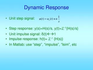
Chapter 12 BJT Dynamic Response Modeling Turn-On Transient • During the turn-on transient: • The general solution is: • Initial condition: QB(0)=0, since transistor is in cutoff: tr: rise time, period of active mode
Chapter 12 BJT Dynamic Response Modeling Turn-On Transient IBBtB > ICCtt bdcIBB > ICC bdc > ICC/IBB • In saturation mode: bdc > bdc(saturation)
Chapter 12 BJT Dynamic Response Modeling Turn-Off Transient • During the turn-off transient: • The general solution is: • Initial condition: QB(0)=IBBtB: tsd : storage delay time
Chapter 12 BJT Dynamic Response Modeling Turn-Off Transient • The transient speed of a BJT depends on the amount of excess minority-carrier charge stored in the base and also the recombination lifetime tB. • By reducing tB, the carrier removal rate is increased, for example by adding recombination centers (Au atoms) in the base. • Tradeoff: bdc= tB/tt will decrease.
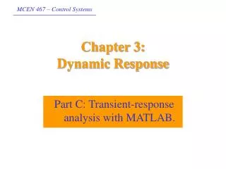
Chapter 12 BJT Dynamic Response Modeling Practical Considerations • The foregoing analysis was highly simplified to avoid excessive amount of mathematics. • More realistic iC transient response is shown below. • Added delay timetd (due to charging of junction capacitance)and fall timetf. Collector current (mathematical model) Collector current (actual form)
Chapter 12 BJT Dynamic Response Modeling Homework 8 • 1. (Int.0) • A pnp BJT has αF = 0.99, αR = 0.1, and IF0 = 10–16 A. If VBC = –0.68 V and IC = 0.1 mA, determine the mode of the device and the value of IB using the Ebers-Moll model. • Deadline: 05.07.2012, at 08:00 am.