Download
1 / 39
390 likes | 642 Views
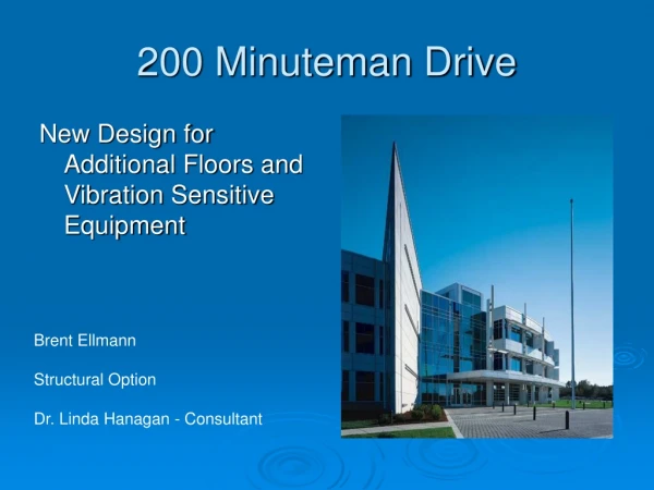
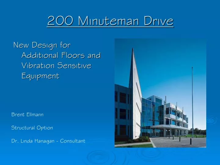
200 Minuteman Drive. New Design for Additional Floors and Vibration Sensitive Equipment. Brent Ellmann Structural Option Dr. Linda Hanagan - Consultant . Project Players. Owner- Brickstone Properties Architects-Burt Hill Kosar Rittleman Associates

E N D
200 Minuteman Drive New Design for Additional Floors and Vibration Sensitive Equipment Brent Ellmann Structural Option Dr. Linda Hanagan - Consultant
Project Players • Owner- Brickstone Properties • Architects-Burt Hill Kosar Rittleman Associates • Structural Engineers- Atlantic Engineering Services • MEP Firm- H. F. Lenz Co. • C M Firm- Gilbane Building Company • Geotechnical Firm- Miller Engineering and Testing, Inc.
Existing Building Conditions • Location: Andover, MA • 3 stories with 200,000 square feet of office space • Cost: $15 million • Designed and built with PictureTel Inc. as primary tenant
Existing Structure • Composite Floor System • 4 inch slab + 2 inch deck • W18x35 beams and W24x76 girders • K Joist Roof System • Square footings and strip footings • Braced frames
Existing Structure • Composite Floor System • K Joist Roof System • 22K6 joists supported by W24x55 girders • W18x35 beams used to support rooftop AHUs • Square footings and strip footings • Braced frames
Existing Structure • Composite Floor System • K Joist Roof System • Square footings and strip footings • Square footings range in size from 5’-0” x 5’-0” to 10’-0” x 10’-0” • Strip footings vary in size from 1’-2” to 2’-8” wide • Braced frames
Existing Structure • Composite Floor System • K Joist Roof System • Square footings and strip footings • Braced frames • Steel Tube and W shapes used as cross braces • Maximum brace width limited to 10” to maintain wall thicknesses
Existing Mech./Elec./Arch. • Mechanical • 6 air handling units with DX cooling coils (25,000 CFM) and ducted supply with a plenum return VAV system • 2 cast iron- sectioned boilers (Gross Output – 2103 MBH) • Electrical • Main switchboard is a 480 Volt/2500 Amp switchboard • Typical light is a three tube FO32/T-8 fluorescent fixture • Architectural • Insulated metal panels, with low-E reflective glazing, on the southern façade • Northern facing curved facade is a limestone veneer, with low-E reflective glazing
Presentation Outline • New Building Height and Floor Sizes by Code • Mechanical (Breadth) • Increased Air Handling Capacity • Duct Sizing • Boiler Design • Electrical (Breadth) • Increased switchboard capabilities • Structural (Emphasis) • Floor Vibration Study • Braced Frame Design • Foundation Design
Goals of New Design • Maintain owner’s original wishes while adding additional floors • All steel building • Open office plan to allow for future tenant changes • Improve performance of floor under vibration excitement due to walking for sensitive equipment • Allow for varying use of building by multiple tenants at once
Code Limits(Per 780 CMR: The Massachusetts State Building Code) • Classified as a 2B Protected Building • Maximum Height • 85’ (with sprinklers) • Maximum Number of Stories • 6 Stories (with sprinklers) • Maximum Allowable Floor Area • 74,250 square feet per floor
New Design • 14’-7” floor to floor heights • 10’-0” clerestory maintained • New building height is 82’-11” • Floor Areas: • First Floor: 67,765 sq. ft. • 2nd-5th Floors: 65,800 sq. ft. • Total Floor Area: 331,000 sq. ft.
Presentation Outline • New Building Height and Floor Sizes by Code • Mechanical (Breadth) • Increased Air Handling Capacity • Duct Sizing • Boiler Design • Electrical (Breadth) • Increased switchboard capabilities • Structural (Emphasis) • Floor Vibration Study • Braced Frame Design • Foundation Design
Mechanical Design • Each half of a floor has own dedicated AHU to maintain multi-tenant capabilities • 10 AHUs located on roof -25,000 cfm each • All vertical runs from AHUs to floor are 84x32 rectangular ducts • Two Zones • Exterior Zone – air supplied through linear diffusers attached to fan boxes (200 cfm) with reheat capability • Interior Zone – air supplied by VAV boxes (160 cfm) • New Cast Iron Boilers • 3500 A-G-14 Series - net output of 3187 MBH (required output = 3050 MBH)
Presentation Outline • New Building Height and Floor Sizes by Code • Mechanical (Breadth) • Increased Air Handling Capacity • Duct Sizing • Boiler Design • Electrical (Breadth) • Increased switchboard capabilities • Structural (Emphasis) • Floor Vibration Study • Braced Frame Design • Foundation Design
New Switchboard • 3,500 Amp Busing • 65,000 Amp Short Circuit Rating
Presentation Outline • New Building Height and Floor Sizes by Code • Mechanical (Breadth) • Increased Air Handling Capacity • Duct Sizing • Boiler Design • Electrical (Breadth) • Increased switchboard capabilities • Structural (Emphasis) • Floor Vibration Study • Braced Frame Design • Foundation Design
Floor Vibration Criteria • Goal: Allow for a variety of technology and research based companies to use this facility • Design carried out using Design Guide 11 and the development of a spreadsheet • Sensitive equipment limit set at that of laboratory robots • Maximum Vibration Velocity – 4,000 μin/sec
Compared Systems Original System New System
Braced Frame Design-Loads • Wind • Basic Wind Velocity = 90 mph • Exposure Category B • Frequency = 2.00 Hz • Pressure = 18 psf • Seismic • SS = 0.30 g and S1 = 0.09 g • T = 0.50 seconds • Seismic Design Category B • W = 35,390 kips; CS = 0.058; V = 2,053 kips
Critical Loading Wind Loads Seismic Loads C R I T I C A L • Low building height results in small wind pressures • Building’s location in an area of higher seismicity results in larger than normal seismic forces
Frame Locations Critical Design Frames
Frame H-34 (N-S) • Columns: W12x72 W12X152 • Braces: • Beams:
Frame H-34 (N-S) • Columns: W12x72 W12X152 • Braces: W10x33 W10x49 • Beams:
Frame H-34 (N-S) • Columns: W12x72 W12X152 • Braces: W10x33 W10x49 • Beams: W24x55 W27x84
Frame 3-HJ (E-W) • Columns: W12x72 W12X152 • Braces: • Beams:
Frame 3-HJ (E-W) • Columns: W12x72 W12X152 • Braces: TS10x10x1/2 • Beams:
Frame 3-HJ (E-W) • Columns: W12x72 W12X152 • Braces: TS10x10x1/2 • Beams: W24x94 W24x162
Foundation Design • Square footings used under columns and strip footings used around perimeter of building • Engineered soil placed under footings • Compressive Strength = 6,000 psf • 3,000 psi concrete used for all footings
Critical Frame Footings • Worst Case Load: • Axial Load = 1,620 Kips • Moment = 220 foot-kips • Double Layer of reinforcing steel needed to fit spacing requirements • Pier size increased to 3’-0” to handling bearing requirements
Uplift Force • Problem: • Earthquake forces develop large uplift on footings • Solution: • Grade Beam attaching to adjacent footings
Grade Beam • 3’-0” x 5’-0” beam spanning over four square footings • Double layer of steel used in both faces • Bottom of beam lines up with bottom of footings
Conclusions • Two floors can be added onto the original design • New Building Height = 82’-11” • Usable Office Space = 330,000 sq. ft. • Mechanical Systems: • Four more AHUs placed on roof (10 total) • Boilers capacity increased by 1000 MBH each • Electrical Systems: • Dual Main-tie-main switchboard increased to a 3,500 amp busing switchboard
Conclusions • Floor System: • Change to a non-composite system to reduce floor vibrations to a level acceptable for a wider variety of sensitive equipment • Braced Frames: • Building’s taller height and large lateral forces required stiffer frames • Foundations: • Grade beam added to handle large uplift forces developed on the square footings under the braced frames
Thank You William McGhee - H.F. Lenz Andrew Verrengia - Atlantic Engineering Services Dr. Linda Hanagan- Structural Consultant Katie Trail – Electrical and Lighting Emphasis Sam Snyder – Mechanical Emphasis Friends and Family