Download
1 / 79
820 likes | 1.02k Views
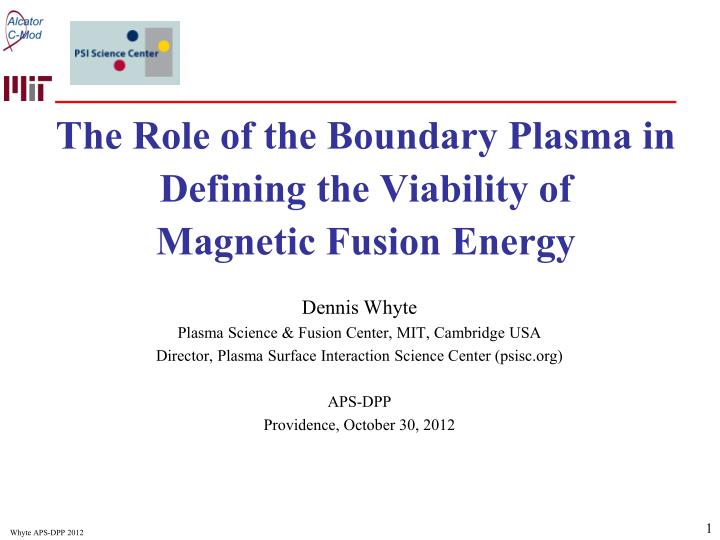
The Role of the Boundary Plasma in Defining the Viability of Magnetic Fusion Energy. Dennis Whyte Plasma Science & Fusion Center, MIT, Cambridge USA Director, Plasma Surface Interaction Science Center (psisc.org) APS-DPP Providence, October 30, 2012. Overview.

E N D
The Role of the Boundary Plasma in Defining the Viability of Magnetic Fusion Energy Dennis Whyte Plasma Science & Fusion Center, MIT, Cambridge USA Director, Plasma Surface Interaction Science Center (psisc.org) APS-DPP Providence, October 30, 2012
Overview • Boundary and PMI (Plasma-Materials Interaction) is too large and multi-disciplinary to cover any single topic in detail • Views expressed are my own • For efficiency the “standard” path of MFE is mostly assumed & assessed: tokamaks, solid-walls, etc. producing base-load electricity Takeaway messages • The boundary issues of power density, pulse duration & high material T are the “right” problems to work on because they are directly and critically involved in making MFE a practical and attractive energy source • The boundary issues involve interconnected and complex physical processes – they will not be solved by “technology” alone
Acknowledging the support of numerous colleagues in boundary & PMI research • B. Lipschultz, P. Stangeby, B. LaBombard, J. Terry, G. Wright, T. Leonard, A. Hubbard, C. Wong, R. Doerner, B. Wirth, D. Buchenauer, G. Matthews, S. Krasheninnikov, R. Goldston, J. Hughes, R. Sullivan, D. Rudakov, R. Maingi, P. Snyder, P. Coad, M. Mayer, G. de Temmerman, R. Neu, G. van Rooij, S. Harrison, M. Reinke, E. Marmar, M. Greenwald, S. Allen, M. Fenstermacher, C. Lasnier, J. Boedo, J.P. Allain, J. Brooks, A. Mahdavi, B. Terreault, B. Gregory..Students: Z. Hartwig, H. Barnard, R. Ochoukov, G. Olynyk, B. Sorbom, D. Brunnerand the late Phil West (GA) who was largely responsible for my start in this field
Fusion Boundary Challenge: Every Joule of energy is extracted through a distant surface with small area to volume ratio Fission Fusion
Boundary challenge from physics viewpoint:The plasma-facing surface is an “extreme interface”
Boundary challenge from physics viewpoint:and physics does not stop at the material!
Boundary challenge from physics viewpoint:and physics does not stop at the material! Progression of talk
Boundary challenge from power plant viewpoint: ITER example Pfusion = 500 MW Sarea = 700 m2 Cost ~ 20 G$ Twall ~ 450 K fon~0.1 (duty factor)
Boundary challenge from power plant viewpoint: ITER example Pfusion = 500 MW Sarea = 700 m2 Cost ~ 20 G$ Twall ~ 450 K fon~0.1 (duty factor)
Boundary challenge from power plant viewpoint: ITER example Pfusion = 500 MW Sarea = 700 m2 Cost ~ 20 G$ Twall ~ 450 K fon~0.1 (duty factor) Pf x 5 2500 MW
Boundary challenge from power plant viewpoint: ITER example Pfusion = 500 MW Sarea = 700 m2 Cost ~ 20 G$ Twall ~ 450 K fon~0.1 (duty factor) Pf x 5 2500 MW ηth x 2 0.5
Boundary challenge from power plant viewpoint: ITER example Pfusion = 500 MW Sarea = 700 m2 Cost ~ 20 G$ Twall ~ 450 K fon~0.1 (duty factor) Pf x 5 2500 MW ηth x 2 0.5 fon x 10 1
Boundary challenge from power plant viewpoint:Viability directly linked to boundary challenges ITER example Pfusion = 500 MW Sarea = 700 m2 Cost ~ 20 G$ Twall ~ 450 K fon~0.1 (duty factor) Pf x 5 2500 MW ηth x 2 0.5 fon x 10 1 Pf / S ~ 4 MW m-2 Twall > 1000 K > yr-long fluence
Robust arguments hold regardless of configurationT > 1000K, Pf / S ~ 3-4 MW/m2 , > 30,000,000 s http://aries.ucsd.edu/ARIES/DOCS/bib.shtml
Boundary “Chasm”to FNSF/Reactors:But these are the right problems to work on for MFE viability
Global power exhaust: Pheat/S ~ 1 MW m-2 a severe challenge due to local limit ~ 5-10 MW m-2 of actively cooled Plasma Facing Components
Global power exhaust: Pheat/S ~ 1 MW m-2 a severe challenge due to local limit ~ 5-10 MW m-2 of actively cooled Plasma Facing Components
Global power exhaust: Pheat/S ~ 1 MW m-2 a severe challenge due to local limit ~ 5-10 MW m-2 of actively cooled Plasma Facing Components Excellent control of power dissipation will be required
Global power exhaust: Pheat/S ~ 1 MW m-2 a severe challenge due to local limit ~ 5-10 MW m-2 of actively cooled Plasma Facing Components Sdivertor/ Sblanket~ 10% Regardless of Configuration ARIES-CS ARIES-ST ARIES-AT http://aries.ucsd.edu/ARIES/DOCS/bib.shtml
Plasma power exhaust is a complex, dealing with many facets of plasma and confinement physicsOngoing efforts required for confidence in extrapolation
Plasma power exhaust is a complex, dealing with many facets of plasma and confinement physicsOngoing efforts required for confidence in extrapolation Issues • Pedestal stability • Neo-classical drifts • Turbulent cross-field transport • // to B (Spitzer, pressure balance) • Atomic physics dissipation • Sheath physics M. Makowski NO4 Wed. AM
Plasma power exhaust is a complex, dealing with many facets of plasma and confinement physicsOngoing efforts required for confidence in extrapolation Issues T. Eich IAEA 2012 • Pedestal stability • Neo-classical drifts • Turbulent cross-field transport • // to B (Spitzer, pressure balance) • Atomic physics dissipation • Sheath physics R. Goldston TP8.00034 Thur AM
Plasma power exhaust is a complex, dealing with many facets of plasma and confinement physicsOngoing efforts required for confidence in extrapolation Issues • Pedestal stability • Neo-classical drifts • Turbulent cross-field transport • // to B (Spitzer, pressure balance) • Atomic physics dissipation • Sheath physics J. Terry, S. Zweben, G. McKee
Plasma power exhaust is a complex, dealing with many facets of plasma and confinement physicsOngoing efforts required for confidence in extrapolation Issues • Pedestal stability • Neo-classical drifts • Turbulent cross-field transport • // to B (Spitzer, pressure balance) • Atomic physics dissipation • Sheath physics Whyte PSI 2012
Plasma power exhaust is a complex, dealing with many facets of plasma and confinement physicsOngoing efforts required for confidence in extrapolation Issues • Pedestal stability • Neo-classical drifts • Turbulent cross-field transport • // to B (Spitzer, pressure balance) • Atomic physics dissipation • Sheath physics Fenstermacher Phys. Plasma 4 (1997)
Plasma power exhaust is a complex, dealing with many facets of plasma and confinement physicsOngoing efforts required for confidence in extrapolation Issues • Pedestal stability • Neo-classical drifts • Turbulent cross-field transport • // to B (Spitzer, pressure balance) • Atomic physics dissipation • Sheath physics D. Brunner APS 2010
Plasma and PFC geometry critical in power exhaust Tradeoffs between flux expansion & tile alignment Vertical Target In C-Mod Snowflake in NSTX • Magnetic topology altered to increase flux expansion at target + promote radiative dissipation • Vertical target • Snowflake • Super-X • But such flux-expansion = 1 degree incident B angle • Must never get leading edges! B. Lipschultz APS2012 V. Soukhanovskii PSI 2012
The available operation window that satisfies heat exhaust and core requirements will be smaller in reactorsExcellent use/control of radiated species required DIII-D: Hybrid H-mode + Ar radiative divertor • Divertor solutions require high density: Tdiv ~ 1/ nSOL2 &Prad ~ n2 Petrie IAEA FEC 2006
The available operation window that satisfies heat exhaust and core requirements will be smaller in reactorsExcellent use/control of radiated species required Hughes NF 51 (2011) DIII-D: Hybrid H-mode + Ar radiative divertor • Divertor solutions require high density: Tdiv ~ 1/ nSOL2 &Prad ~ n2 • But reactor SOL has important tradeoffs • Greenwald ne limit • Current drive efficiency ICD/P~ 1 / ne • Pedestal/separatrix pressure? • Confinement (Pped) vs. core Prad Pouter-div / Pheat Alcator C-Mod: Impurity seeding reducing Pdiv at P/S ≤ 0.72 MWm-2 @ H98 ~ 1 Petrie IAEA FEC 2006
A reactor requires high plasma pressure & energy density which will damage materials if transiently released
A reactor requires high plasma pressure & energy density which will damage materials if transiently releasedReactor transient challenge 3x ITER TungstenBeforeexposure ARIES-ST ARIES-AT Ideal W Melt limit ARIES-RS Transient energy density (Wth/S/s1/2) After5 “large” ELMs ~30 MJ/m2/s1/2 Realistic W Transient limit ITER 30 mm Klimov PSI 2008
Critical development for MFE reactors: Regimes with adequate pedestal but which are not regulated by large instability I-mode on C-Mod /w RF only QH-mode on DIII-D /w τexternal~0 K. Burrell IAEA 2012 A, HubbardIAEA 2012
Critical development for MFE reactors: Regimes with adequate pedestal but which are not regulated by large instability I-mode on C-Mod /w RF only QH-mode on DIII-D /w τexternal~0 + external methods such as pacing & RMP coils But all choices have design consequences in reactor
Recent example of JET changing to metal (ITER-like) wall re-emphasizes critical role of PFC choice in global performance & scenarios • Motivated by tritium retention concerns in ITER for carbon • X10 reduction found with metals • But also modifications to H-mode threshold and to pedestal! R. Neu GI-2 Tues AM
Recent example of JET changing to metal (ITER-like) wall re-emphasizes critical role of PFC choice in global performance & scenarios • Motivated by tritium retention concerns in ITER for carbon • X10 reduction found with metals • But also modifications to H-mode threshold and to pedestal! Neu XXX
Recent example of JET changing to metal (ITER-like) wall re-emphasizes critical role of PFC choice in global performance & scenarios • Motivated by tritium retention concerns in ITER for carbon • X10 reduction found with metals • But also modifications to H-mode threshold and to pedestal! Core, boundary and PFC are inextricably linked in a successful reactor design Neu XXX
Critical MFE reactordesign goals for PFCs • Continuous > 1 year (31,000,000 s) operation without need for replacement. • High resistance to erosion < mm /year by plasma ions and CX neutrals • Low tritium storage: < 1 kg in PFCs (safety and tritium economy) • Minimize free matter (dust, particulates, films) for safety + plasma
Power density + duration • Divertor PFC must be thin ~ 2-5 mm for heat conduction • q=10 MW/m2 ~ 100 K/mm for W
Power density + duration • Divertor PFC must be thin ~ 2-5 mm for heat conduction • q=10 MW/m2 ~ 100 K/mm for W • Tdiv< 10 eV required for heat exhaust but still ~ 10 MW/m2 • Yearly fluence of D-T-He ions through sheath: 4x1031 ions / m2 • Areal density of 1 mm solid:6x1025 W atoms / m2
Power density + duration:Divertor erosion resistance for > year-long viability poses a severe challenge PFC choice of tungsten • Divertor PFC must be thin ~ 2-5 mm for heat conduction • q=10 MW/m2 ~ 100 K/mm for W • Tdiv< 10 eV required for heat exhaust but still ~ 10 MW/m2 • Yearly fluence of D-T-He ions through sheath: 5x1031 ions / m2 • Areal density of 1 mm solid:6x1025 atoms / m2 • Conclusion: net loss “yield” of divertor atoms < 10-6 atom/ion • Sputtering must be turned off.
Power density + duration:Divertor erosion resistance for > year-long viability poses a severe challenge PFC choice of tungsten Tungsten yield In ASDEX-U divertor • Divertor PFC must be thin ~ 2-5 mm for heat conduction • q=10 MW/m2 ~ 100 K/mm for W • Tdiv< 10 eV required for heat exhaust but still ~ 10 MW/m2 • Yearly fluence of D-T-He ions through sheath: 5x1031 ions / m2 • Areal density of 1 mm solid:6x1025 atoms / m2 • Conclusion: net loss “yield” of divertor atoms < 10-6 atom/ion • Sputtering must be turned off. Achieving Tdiv<10 eV necessary For both erosion & heat flux control Krieger JNM 266-269 (1999)
Campaign integrated divertor tungsten erosion in present devices ASDEX-Upgrade Alcator C-Mod W film On C Solid W 1020W m-2 Barnard JNM 415 (2011) Mayer Phys. Scr. T138 (2009)
Even with tungsten’s superior erosion resistance, demonstrated divertor erosion rate must be decreased further • Campaign integrated using wide variety of divertor plasmas • But reactor must have ndiv~1021 m-3 Tdiv~10 eV continuously. • Erosion / deposition from complex interplay of erosion + transport • Calls for in-situ erosion measurement 1M Mayer et al., Phys. Scr. T128 (2007) 106 2H. Barnard et al., J. Nucl. Mater. 415 (2011) S301
In-situ diagnostics must be developed to provide instantaneous erosion rates in our present confinement devicesAGNOSTIC on C-Mod • RFQ linear accelerator injects 0.9 MeV D+ beam into vacuum vessel • Tokamak B files provide steering • D+ induces high-Q nuclear reactions in PFC surfaces producing ~MeV neutrons and gammas • Advanced in-vessel neutron and gamma spectroscopy + GEANT4 model Hartwig, et al, Rev. Sci. Instrum 2010
In-situ diagnostics must be developed to provide instantaneous erosion rates in our present confinement devicesFirst in-situ surface measurements Summer 2012 Boron Gamma spectra resulting from D-induced nuclear reactions at two poloidal locations e+ annihilation Oxygen
Charge-exchange neutral erosion of first-wall material long-range migration how to deal with tonnes of “debris”? • Diffuse, energetic CX neutrals impinge on blanket surface. • Likely migration result: // transport to divertor Behrisch JNM 313-316 (2003)
The plasma-surface interface is perturbing & complex e.g. the divertor surface is reconstituted ~100 times per second Wirth, Whyte, et al MRS 2011
The plasma-material interface never comes to full equilibrium because the fusion environment perpetually evolves the surface and material properties
And even with a constant plasma, erosion/deposition changes material temperatures Evolving, exponentially sensitive boundary response Arrheniusrates