Download
1 / 39
390 likes | 404 Views
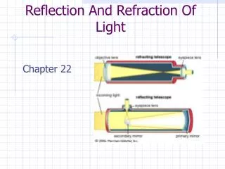
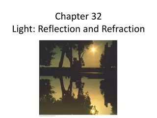
Chapter 32 Light: Reflection and Refraction. Mirrors and Lenses. Chapter 34 The Wave Nature of Light; Interference. Units of Chapter 34. Waves versus Particles; Huygens’ Principle and Diffraction Huygens’ Principle and the Law of Refraction Interference – Young’s Double-Slit Experiment

E N D
Units of Chapter 34 • Waves versus Particles; Huygens’ Principle and Diffraction • Huygens’ Principle and the Law of Refraction • Interference – Young’s Double-Slit Experiment • Intensity in the Double-Slit Interference Pattern • Interference in Thin Films • Michelson Interferometer • Luminous Intensity
34-1 Waves versus Particles; Huygens’ Principle and Diffraction Huygens’ principle: every point on a wave front acts as a point source; the wave front as it develops is tangent to all the wavelets.
34-1 Waves versus Particles; Huygens’ Principle and Diffraction Huygens’ principle is consistent with diffraction:
34-2 Huygens’ Principle and the Law of Refraction Huygens’ principle can also explain the law of refraction. As the wavelets propagate from each point, they propagate more slowly in the medium of higher index of refraction. This leads to a bend in the wave front and therefore in the ray.
34-2 Huygens’ Principle and the Law of Refraction The frequency of the light does not change, but the wavelength does as it travels into a new medium:
34-2 Huygens’ Principle and the Law of Refraction Highway mirages are due to a gradually changing index of refraction in heated air.
34-3 Interference – Young’s Double-Slit Experiment If light is a wave, interference effects will be seen, where one part of a wave front can interact with another part. One way to study this is to do a double-slit experiment:
34-3 Interference – Young’s Double-Slit Experiment If light is a wave, there should be an interference pattern.
34-3 Interference – Young’s Double-Slit Experiment The interference occurs because each point on the screen is not the same distance from both slits. Depending on the path length difference, the wave can interfere constructively (bright spot) or destructively (dark spot).
34-3 Interference – Young’s Double-Slit Experiment We can use geometry to find the conditions for constructive and destructive interference: and
34-3 Interference – Young’s Double-Slit Experiment Between the maxima and the minima, the interference varies smoothly.
34-3 Interference – Young’s Double-Slit Experiment Conceptual Example 34-1: Interference pattern lines. (a) Will there be an infinite number of points on the viewing screen where constructive and destructive interference occur, or only a finite number of points? (b) Are neighboring points of constructive interference uniformly spaced, or is the spacing between neighboring points of constructive interference not uniform?
34-3 Interference – Young’s Double-Slit Experiment Example 34-2: Line spacing for double-slit interference. A screen containing two slits 0.100 mm apart is 1.20 m from the viewing screen. Light of wavelength λ = 500 nm falls on the slits from a distant source. Approximately how far apart will adjacent bright interference fringes be on the screen?
34-3 Interference – Young’s Double-Slit Experiment Conceptual Example 34-3: Changing the wavelength. (a) What happens to the interference pattern in the previous example if the incident light (500 nm) is replaced by light of wavelength 700 nm? (b) What happens instead if the wavelength stays at 500 nm but the slits are moved farther apart?
34-3 Interference – Young’s Double-Slit Experiment Since the position of the maxima (except the central one) depends on wavelength, the first- and higher-order fringes contain a spectrum of colors.
34-3 Interference – Young’s Double-Slit Experiment Example 34-4: Wavelengths from double-slit interference. White light passes through two slits 0.50 mm apart, and an interference pattern is observed on a screen 2.5 m away. The first-order fringe resembles a rainbow with violet and red light at opposite ends. The violet light is about 2.0 mm and the red 3.5 mm from the center of the central white fringe. Estimate the wavelengths for the violet and red light.
34-4 Intensity in the Double-Slit Interference Pattern The electric fields at the point P from the two slits are given by . where
34-4 Intensity in the Double-Slit Interference Pattern The two waves can be added using phasors, to take the phase difference into account:
34-4 Intensity in the Double-Slit Interference Pattern The time-averaged intensity is proportional to the square of the field:
34-4 Intensity in the Double-Slit Interference Pattern This plot shows the intensity as a function of angle.
34-4 Intensity in the Double-Slit Interference Pattern Example 34-5: Antenna intensity. Two radio antennas are located close to each other, separated by a distance d. The antennas radiate in phase with each other, emitting waves of intensity I0 at wavelength λ. (a) Calculate the net intensity as a function of θ for points very far from the antennas. (b) For d = λ, determine I and find in which directions I is a maximum and a minimum. (c) Repeat part (b) when d = λ/2.
34-5 Interference in Thin Films Another way path lengths can differ, and waves interfere, is if they travel through different media. If there is a very thin film of material – a few wavelengths thick – light will reflect from both the bottom and the top of the layer, causing interference. This can be seen in soap bubbles and oil slicks.
34-5 Interference in Thin Films The wavelength of the light will be different in the oil and the air, and the reflections at points A and B may or may not involve phase changes.
34-5 Interference in Thin Films A similar effect takes place when a shallowly curved piece of glass is placed on a flat one. When viewed from above, concentric circles appear that are called Newton’s rings.
34-5 Interference in Thin Films A beam of light reflected by a material with index of refraction greater than that of the material in which it is traveling, changes phase by 180° or ½ cycle.
34-5 Interference in Thin Films Example 34-6: Thin film of air, wedge-shaped. A very fine wire 7.35 x 10⁻³ mm in diameter is placed between two flat glass plates. Light whose wavelength in air is 600 nm falls (and is viewed) perpendicular to the plates and a series of bright and dark bands is seen. How many light and dark bands will there be in this case? Will the area next to the wire be bright or dark?
34-5 Interference in Thin Films Example 34-7: Thickness of soap bubble skin. A soap bubble appears green (λ = 540 nm) at the point on its front surface nearest the viewer. What is the smallest thickness the soap bubble film could have? Assume n = 1.35.
34-5 Interference in Thin Films • Problem Solving: Interference • Interference occurs when two or more waves arrive simultaneously at the same point in space. • Constructive interference occurs when the waves are in phase. • Destructive interference occurs when the waves are out of phase. • An extra half-wavelength shift occurs when light reflects from a medium with higher refractive index.
34-5 Interference in Thin Films Example 34-8: Nonreflective coating. What is the thickness of an optical coating of MgF2 whose index of refraction is n = 1.38 and which is designed to eliminate reflected light at wavelengths (in air) around 550 nm when incident normally on glass for which n = 1.50?
34-6 Michelson Interferometer The Michelson interferometer is centered around a beam splitter, which transmits about half the light hitting it and reflects the rest. It can be a very sensitive measure of length.
34-7 Luminous Intensity The intensity of light as perceived depends not only on the actual intensity but also on the sensitivity of the eye at different wavelengths. Luminous flux: 1 lumen = 1/683 W of 555-nm light Luminous intensity: 1 candela = 1 lumen/steradian Illuminance: luminous flux per unit area
34-7 Luminous Intensity Example 34-9: Lightbulb illuminance. The brightness of a particular type of 100-W lightbulb is rated at 1700 lm. Determine (a) the luminous intensity and (b) the illuminance at a distance of 2.0 m.
Summary of Chapter 34 • The wave theory of light is strengthened by the interference and diffraction of light. • Huygens’ principle: every point on a wave front is a source of spherical wavelets. • Wavelength of light in a medium with index of refraction n: • Young’s double-slit experiment demonstrated interference.
Summary of Chapter 34 • In the double-slit experiment, constructive interference occurs when • and destructive interference when • Two sources of light are coherent if they have the same frequency and maintain the same phase relationship.
Summary of Chapter 34 • Interference can occur between reflections from the front and back surfaces of a thin film. • Light undergoes a 180° phase change if it reflects from a medium of higher index of refraction.