Download

1 / 38
380 likes | 577 Views
An-Najah National University Civil Engineering Department Analysis of the Water Distribution Network of Almasaken-Nablus Submitted by: Samar Bishawi Suha Awad Supervisor: Dr. Mohammad N . Almasri 2010.

E N D
An-Najah National UniversityCivil Engineering DepartmentAnalysis of the Water Distribution Network of Almasaken-Nablus Submitted by: Samar Bishawi Suha Awad Supervisor: Dr. Mohammad N . Almasri 2010
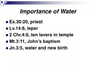
The importance of water distribution networks • Distribution systems move water from the source to the consumer . In situations of having population growth, increasing demand for water and shrinking water sources make these systems to become more vital than ever before. • The water in any distribution system may become contaminated if the sources were not protected and monitored in an appropriate manner, or treatment plants were not working properly, or no maintenance of infrastructure
The main objectives Assess the water consumption in Almasaken area. Analyze hydraulically the water distribution network of Almasaken by using EPANET.
Study area The population of Almsaken Alshaabia is 4000 persons. Water source for Almsaken Alshaabia is Al-Baddan well The highest elevation in the area is 538 m and the lowest is 405 m
Methodology • Information and data collection: • These include the nature of the area, its climate, water resources ,per capita water consumption , statistics information and contour map. In addition , interviews were made with municipality employees, etc. • Data preparation using GIS and Excel. • Evaluate the network under current condition in terms of population size using the computer program (EPANET). • Evaluate the network under the scenario obtain of future population increase • State the main conclusions .
Network Development • The GIS file which is taken from the • Municipal, has several layers :_ • Road layer • Nablus Contour layer , • Water house connection , • Water main connection and • building layer .
Preparing the map making Thiessen polygons. Thiessen Polygons are used to predict the values at surrounding point . Thiessen polygons have the unique property that each polygon contains only one input point. The Thiessen polygons are constructed as follows : At first we make an area that limits the study area.
By using GIS analyses tools Thiessen Polygons were created .
Transferring the Map to EPANET The Shp2epa program was used to transfer the map from the GIS to EPANET.
Preparing the data required for the EPANET analyze The data required in the EPANET program is the base demand and the elevation for the junctions and pipe type ,length and diameter for the pipe and need data for pump. For the base demand the following procedure used to calculate it :_ 1_By using the GIS program, select Analysis tool _Overlay _ Intersect. Then we use this order between the Thiessen ID and the building area ID.
2_from the attribute table, we find the area of the building in every thiessen according to its ID. 3_To know the point ID with respect to the thiessen ID we made intersect between them. 4_the area in the attribute table is multiplied by the density . 5_The result is the population in every thiessen. This number is multiplied by the water consumption per capita which equals 80 L/c-day.
For the elevation from the GIS file we have the contour layer of the study area used to find the elevation for every node by using the identify order
According to the coordination of the nodes, it is transferred to the EPANET file by using the GIS, following these steps. According to the pipe data : When the program shp2epa is used to transfer the file to the EPANET automatically the length of the pipe is found in the EPANET file .
The pipe type is important to determine the roughness coefficient by using the identify tool in the GIS or the attribute table we find that the pipes made of steel , by using the same way the diameter of pipes were found . According to the pump : The pump characteristic curve ,the data required was the flow at which the pump work and the head corresponding to it which was (200 CMH) (380m) respectively
The analyses in this chapter done for three cases: Existing steady state . Transient steady state for the existing condition. Future network analyses.
Existing steady state . According to the pressure there is no negative pressure , the highest pressure was 175 m and the lowest pressure was 33 m .
The relation between the pressure and the elevation was inverse proportion
According to the velocity, the results were within the range (0.3-2) m/sec. There is no velocity above 2 m/sec and there are some pipes with velocity below 0.2 m/sec .
2_Transient state in the existing condition: In this case the base demand is steady state case ,except the time pattern. In this study , the pattern time step was set to 2 hours . This will cause demands to change at 12 different times of the day.
the relation between the velocity and the time for link 65.
Future network:_ In this case the future analysis for the existing network after 25 years from now . In this case we have two variables , the population and the water consumption per capita . by using the following equation . Pf = Pp * ( 1+i)ⁿ The population after 25 years =7,062 persons .
According to WHO the future consumption range is (100_150). To estimate the future water demand for each node , the existing water demand will be multiplied by a factor . In this case we will change the roughness factor and the losses in the network with the factor ,in three cases.
The current velocity values of the network are in general within the limits, some pipes will be replaced by larger pipes
As we see there are negative pressures in the future case , but we can solve this problem if we replace the existing pump by another pump which flows = 320 CMH at a head = 480 m .The result becomes acceptable where the lowest pressure is 59.7m(Node 2), and the highest pressure is 201m (node 9).
THE END THANKS FOR YOUR ATTENTION