Download
1 / 44
440 likes | 599 Views
Vector Maps - Production Flow ( Portugal - Portimão - 2012 ). Vasco Palmeirim. Introduction. The purpose of this document is to give an example of the power of Photomod software, showing how SIGMAGEO uses PhotoMod in Map Production.

E N D
Vector Maps - Production Flow ( Portugal - Portimão - 2012 ) Vasco Palmeirim
Introduction • The purpose of this document is to give an example of the power of Photomod software, showing how SIGMAGEO uses PhotoMod in Map Production. • The following case will show how Photomod modules helps you produce vector maps, while we present a flow chart of the production phases. SIGMAGEO is a Portuguese Private Company, that is the Photomod distributor for Portugal. We have also Production Departments which deal mainly in GIS and Mapping .
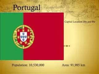
Work location (1) The working area is located about 24 Km West of Portimão, with an area of 482 ha
Work location (2) The area is a bit hilly, but without being rough.
Aerial Photographs • Maximum pixel size (terrain) 5 cm • · File format : uncompressed TIFF, RGB 16 bit color pixel • 60% image overlap inside strips • 30% strip overlap • Global Orthophotomap • ·Scale 1:500 • File format : uncompressed JPEG • TFWgeoreferencefile • · Pixel size : 10 cm • ·Planimetric Precision : 10 cm • State certification • The vector maps and orthophotos must have a certificate from DIRECÇÃOGERAL DO TERRITÓRIO, the former INSTITUTOGEOGRÁFICOPORTUGUÊS. • Global 3D Vector file • · Scale 1:500 • · File format : Autocad 2000 binary DWG • Planimetric Precision : 10 cm • Planimetric Details: Buildings, Road, Walls Slopes, Water lines, … • · Contour lines every 0,5 meter Detailed specifications
Project Planing 1.Aerial photography 2. Ground Control Points (GPS) 3. Block orientation 4. Aerotriangulation with AT module 5. Block adjustment with Solver A module 6. Vector data acquisition with StereoDraw module 7. TIN editing with DTM module 8. Orthorectification with Mosaic and Geomosaic Final editing with CAD software With these parameters set by the client, we planned our production line as follows:
Aerial photographs The flight was done using ZI’sDMCcamera: 4 Strips 107 images IMU/GPS was used
Ground control points (1) Being an area with very few human contact, it was very difficult to choose planimetric details that could be used as good Ground Control Points (GCP). Especial care is always used in choosing points not near to trees and other objects that clouds satellite observations. We always try to choose GCP on ground level, so that is will be easier to observe in stereoscopic viewing. It also prevents human error in antenna height compensation. Good points are sidewalks, white paintings in the roads, sewer cover, etc…
Ground control points (2) When ground detail made it difficult to choose good GCPs, points should subdivided in 2 neighboring points. Even using IMU data, we measured 24 GCP to guarantee the precision of the technical specifications of the client. During fieldwork, we used SOKKIA GPS GSS1 2 band receivers (static mode) recording satellite data every 10 seconds during a minimum of 20 minutes. Coordinates were calculated with post-processing software by Sokkia, thus achieving better than 1 cm precision.
Block / Orientation(1) 1 - Importing images Block forming was very easy using PhotoMod tools:
Block / Orientation(2) 2 – Editing camera parameters Block forming was very easy using PhotoMod tools:
Block / Orientation(3) 3 – Automatic interior orientation Block forming was very easy using PhotoMod tools:
Block / Orientation(4) 4 - Importing external orientation data file Block forming was very easy using PhotoMod tools:
Block / Orientation(5) 5 – Automatic Block Layout Block forming was very easy using PhotoMod tools:
Block / Orientation(6) 6 – Automatic Block Layout – without layout 6 - Automatic Block Layout – by external orientation Block forming was very easy using PhotoMod tools:
Aerotriangulation (1) 1 - Creating manual Strip Ties Aerotriangulation followed the usual sequence in PhotoMod AT module:
Aerotriangulation (2) 2 - Creating automatic Ties Points Because the area has many vegetation and few good planimetric details, we had to create manually 729 Strip and tie points, while automatically we only achieved 402 points. This means a ratio of 64/36% when we use to achieve ratios of 10/90% Aerotriangulation followed the usual sequence in PhotoMod AT module:
Aerotriangulation (3) 3 - Creating the Relative Orientation Report Aerotriangulation followed the usual sequence in PhotoMod AT module:
Aerotriangulation (4) 4 – Using the Relative Orientation Report Aerotriangulation followed the usual sequence in PhotoMod AT module:
Aerotriangulation (5) 5 - Editing points outside given parameters Aerotriangulation followed the usual sequence in PhotoMod AT module:
Aerotriangulation (6) 6 – Importing Ground Control Points data files Aerotriangulation followed the usual sequence in PhotoMod AT module:
Aerotriangulation (7) 7 – Measuring Ground Control Points Aerotriangulation followed the usual sequence in PhotoMod AT module:
Block Adjustment (1) 1 – Choosing parameters for adjustment Block adjustment followed the usual sequence in PhotoMod Solver A module:
Block Adjustment (2) 2 – Control using Free model option Block adjustment followed the usual sequence in PhotoMod Solver A module:
Block Adjustment (3) 3 – Making final adjustments Block adjustment followed the usual sequence in PhotoMod Solver A module:
Block Adjustment (6) 6 – Controlling GCP stereoscopic measurements Block adjustment followed the usual sequence in PhotoMod Solver A module:
Data aquisition (1) 1 – Choosing/creating Codetable Using PhotoMod´sStereoDraw module:
Data aquisition (2) 2 – Vectorizingplanimetric details, such as: Roads Buildings Walls Fences Posts Lakes Rivers Slopes Ridges Bridges etc... Using PhotoMod´sStereoDraw module:
Data aquisition/DTM (1) 1 – From StereoDraw data, we now use 3Ddata which correctly defines earth surface, such as: Water lines, lakes, rivers, slopes, ridges, roads, paths …to make a first TIN 2 – Drawing extra lines and points 3 – Building contour lines with 0,5 m interval 4 – DEM building with 50 cm cell size Using PhotoMod´sDTM module:
Orthorectification(1) 1 – Choosing outside limit of all images Using PhotoMod´s Mosaic module:
Orthorectification(2) 2 – Choosing parameters for orthorectification: DEM Using PhotoMod´s Mosaic module:
Orthorectification(3) 3 – Choosing parameters for orthorectification: Cell size, background color, georeference file Using PhotoMod´s Mosaic module:
Orthorectification(4) 4 – Choosing parameters for orthorectification: Global adjustment Using PhotoMod´s Mosaic module:
Orthorectification(5) 5 – Choosing parameters for orthorectification: No spliting, choosing all images Using PhotoMod´s Mosaic module:
Orthorectification(6) 6 – Viewing all images after orthorectification Using PhotoMod´sGeoMosaic module:
Orthorectification(7) 7 – Choosing cutlines creation parameters Using PhotoMod´sGeoMosaic module:
Orthorectification(8) 8 – Editing cutlines Using PhotoMod´sGeoMosaic module:
Orthorectification(9) 9 – Final sheet spliting, creating the final orthophotos with 10 cm cell size Using PhotoMod´sGeomosaic module:
Vector map 1 - Topologic data control was made, buildings closed, contour labels added, etc… Using CAD software ,all planimetric and height data created were joined in only one drawing
Vector map and ortophoto(1) Controlling orthophoto and vector map
Vector map and ortophoto(2) Detailed close-up
Vector map and ortophoto(3) Another close-up
Final Notes The 5.1 and 5.2 Photomod versions we used in this presentation are very powerful tools for Map Production, even with very precise technical requests from our clients. I must remember, that this paper does not refer many other potential applications that Photomod software modules can do. I am proud to inform that personnally I have been working with Photomod software for the last 12 years, and wish to use this opportunity to congratulate Racurs and all their workers, for the excellent software development that they have been producing along these years.