Download
1 / 17
170 likes | 287 Views
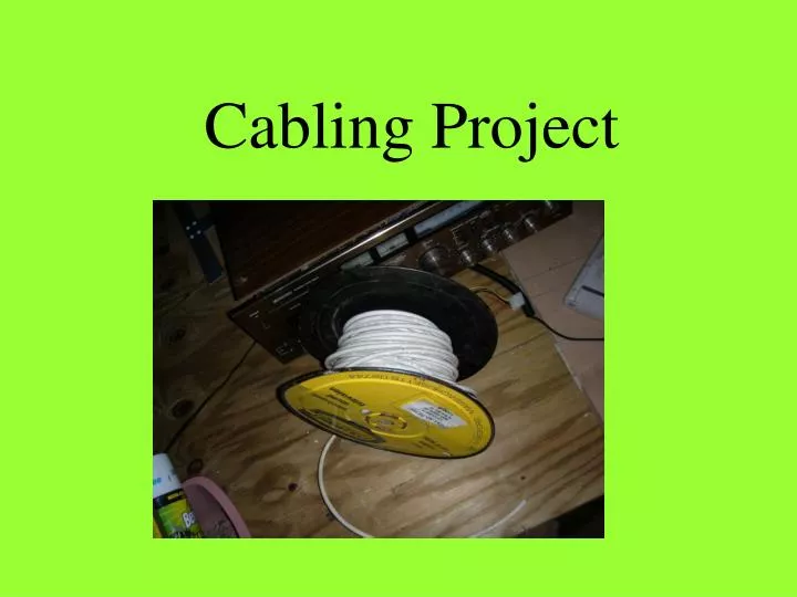
Cabling Project. Your first responsibility, as the network designer, will be to have your client specify, in writing, the desired outcome of the project.

E N D
Your first responsibility, as the network designer, will be to have your client specify, in writing, the desired outcome of the project.
As the designer, you will include written documentation, including fact-finding assessments, work-in-progress reports, and final reports and test results.
The following list includes some of the documentation that you should create while you are in the process of planning/designing your network: • engineering journal • logical topology • physical topology • cut sheets • problem-solving matrices • labeled outlets • labeled cable runs • summary of outlets and cable runs • summary of devices, MAC addresses, and IP addresses
The flowchart should include the following tasks: • installing outlets • installing jacks • running cables • punching cables into patch panels • testing cables • documenting cables • installing NICs • installing hubs, switches, bridges, and routers • configuring routers • installing and configuring PCs
Your plan should include the following: • building materials • suppliers • tools • date and length of time tools required
The telecommunications outlet, in a horizontal cabling scheme, is usually mounted on a wall. EIA/TIA-568B specifies two types of wall mounts that can be used to position an RJ-45 jack onto a wall - the surface mount, and the flush mount.
Next, separate out each pair of twisted wires. The first color that appears on the left side of the jack is blue. Find the pair of wires that contains the blue wire, and untwist them. Lay the blue wire on the slot, on the left, that is color coded blue. Lay the second wire of this pair on the slot, on the right, that is color coded blue and white.
A cut sheet is a rough diagram that shows the locations of the cable runs.
Avoid labeling cables, telecommunications outlets, and patch panels with terms such as "Mr. Zimmerman's math class," or "Ms. Thome's art class". Mr. D’s
Rather than run the cable four times over the same route, your work would be easier, and you would save time, if you routed all four cables at the same time. To do this, you need four spools of cable. Label each cable end.
Allow enough cable for the ends to reach all the way to each jack location plus enough excess or slack to reach the floor and extend another 2'-3'.
Use the labels on each spool as a reference, then mark each cable with the appropriate room number and letter.
Whenever you work in walls, ceilings, or attics, the first thing you should do is turn off power to all circuits that might pass through those work areas! If you are not sure which wires pass through the section of the building in which you are working, a good rule to follow is to shut off all power. Never, ever, touch power cables! Even if you think you have cut all power to the area where you will be working, there is no way to know if they are "live".
Finally, if you find that you must route cable through spaces where air is circulated, you will need to use a fire-rated cable.
In an Ethernet LAN star topology, the horizontal cabling runs, which come from the work areas, usually terminate at a patch panel.
Cable testers, sometimes referred to as time domain reflectometers (TDRs), measure the distance to open-ended, or shorted cable by sending an electrical pulse through the cable. The devices then time the signal's reflection from the end of the cable. This test can provide distance readings that are accurate to within 2 feet.