Download
1 / 33
330 likes | 484 Views
Telecom Cabling. Testing and cable certification. Telecom Cabling. Testing a cable can involve a simple 4 pair test for continuity called wire mapping.

E N D
Telecom Cabling Testing and cable certification
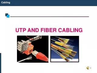
Telecom Cabling • Testing a cable can involve a simple 4 pair test for continuity called wire mapping. • Cable Certification is a much more sophisticated process that involves actually placing a simulated computer signal on the cable and seeing if the installation meets the standards applicable to that category of cabling.
Telecom Cabling • These are some examples of four pair wire mappers, they perform the basic continuity test and some can measure length and even ping hub ports.
Telecom Cabling • Wire mapping tests for opens, shorts, reverse pairs, transposed pairs and split pairs. • This diagram shows a wire map representation that you would see on a cable analyzer.
Telecom Cabling • This diagram shows opens, if this is a 568B wiring configuration what color conductors are open?
Telecom Cabling • This diagram shows a short, if this is a 568A wiring configuration which pair color is shorted?
Telecom Cabling • This diagram shows a reversed pair, what color is the pair and is it reversed at the panel or the jack?
Telecom Cabling • This diagram shows transposed pairs, for a 568B wiring configuration which pairs are transposed?
Telecom Cabling • This diagram shows a split pair at one end of the link, what conductor colors are split? (568B)
Telecom Cabling • Most installations today require a certification report before you will get paid. • These reports are studied by the companies providing the warranty on the project and have people trained to recognize “cheating”. • If anything looks suspect they will perform third party testing to verify the results.
Telecom Cabling • ANSI/TIA/EIA-568-B.2-1 • “Addendum 1 – Transmission Performance Specifications for 4-pair 100 Ω Category 6 Cabling”. • One hundred percent of the installed cabling links must pass the testing requirements.
Telecom Cabling • The test equipment shall comply with the accuracy requirements for level III field testers as defined in the Category 6 Standard. • The tester shall be within the calibration period recommended by the vendor in order to achieve the vendor-specified measurement accuracy. • Any failing link must be diagnosed, corrected and re-tested to prove that the corrected link meets the performance requirements.
Telecom Cabling • Every cabling link in the installation shall be tested for: • Wire Map • Length • Insertion Loss • NEXT Loss • PS NEXT Loss • ACR-F Loss • PS ACR-F Loss • Return Loss • Propagation Delay • Delay Skew
Telecom Cabling • Length:The field tester shall be capable of measuring length of all pairs of a basic link or channel based on the propagation delay measurement and the average value for NVP (nominal velocity of propagation). • The physical length of the link shall be calculated using the pair with the shortest electrical delay. • This length figure shall be reported and shall be used for making the Pass/Fail decision.
Telecom Cabling • Note that at distances beyond 295’ you will get “marginal passes” which mean you pass, but you are at the edge of acceptability.
Telecom Cabling • The Pass/Fail criteria are based on the maximum length allowed for the Permanent Link configuration (90 meters – 295 feet) plus 10% to allow for the variation and uncertainty of NVP.
Telecom Cabling • Insertion Loss (Attenuation):Insertion Loss is a measure of signal loss in the permanent link or channel. The term “Attenuation” has been used to designate “Insertion Loss.” • Insertion Loss shall be tested from 1 MHz through 250 MHz
Telecom Cabling • Minimum test results documentation (summary results): • Identify the worst wire pair (1 of 4 possible). • The test results for the worst wire pair must show the highest attenuation value measured (worst case), the frequency at which this worst case value occurs, and the test limit value at this frequency.
Telecom Cabling • NEXT: • Pair-to-pair near-end crosstalk loss (abbreviated as NEXT Loss) shall be tested for each wire pair combination from each end of the link (a total of 12 pair combinations). • NEXT Loss measures the crosstalk disturbance on a wire pair at the end from which the disturbance signal is transmitted (near-end) on the disturbing pair.
Telecom Cabling • Identify the wire pair combination that exhibits the worst case NEXT margin and the wire pair combination that exhibits the worst value of NEXT (worst case). • NEXT is to be measured from each end of the link-under-test. These wire pair combinations must be identified for the tests performed from each end. Each reported case should include the frequency at which it occurs as well as the test limit value at this frequency.
Telecom Cabling • PS NEXT Loss: • Power Sum NEXT Loss shall be evaluated and reported for each wire pair from both ends of the link under-test (a total of eight results). • PS NEXT Loss captures the combined near-end crosstalk effect on a wire pair when all other pairs actively transmit signals.
Telecom Cabling • ACR-F Loss, pair-to-pair • Attenuation Crosstalk Ratio Far-endis calculated from the pair-to-pair FEXT (far end cross talk) Loss. • It shall be measured for each wire-pair combination from both ends of the link under-test. FEXT Loss measures the crosstalk disturbance on a wire pair at the opposite end (far-end) from which the transmitter emits the disturbing signal on the disturbing pair.
Telecom Cabling • PS ACR-F Loss • Power Sum Attenuation Crosstalk Ratio Far-end is a calculated parameter that combines the effect of the FEXT disturbance from three wire pairs on the fourth one. • This test yields eight wire-pair combinations..
Return Loss • Return Loss • Return Loss (RL) measures the total energy reflected on each wire pair. • Return Loss is to be measured from both ends of the link-under-test for each wire pair.
Telecom Cabling • Delay Skew: • This parameter shows the difference in propagation delay between the four wire pairs. The pair with the shortest propagation delay is the reference pair with a delay skew value of zero.
Telecom Cabling • Propagation Delay: • Propagation delay is the time required for the signal to travel from one end of the link to the other. • This measurement is to be performed for each of the four wire pairs.
Telecom Cabling • Cable certifiers are expensive…around $7,000.00 new. • They also have modules added to them for CAT6, CAT5E, Coax, and Fiber that are very expensive as well. • A certifier is a big investment. • BE CAREFUL WITH THESE.
Telecom Cabling • Always at least 4 pair test every cable. • Chances are, if your wire map is good, continuity is good, and your pull and terminations are good. • YOU WILL BE O.K.
Telecom Cabling • On all large projects the customer is getting a warranty on all network devices installed, the cable, jacks, face plates, patch panels and patch cords. • The certification process confirms that the cable plant will meet all specifications and function effectively for 15 to 20 years (warranty period) at the category installed.
Telecom Cabling • The documentation and labeling lecture comes into play here. • You will use the same WAO identifiers for saving the test results on the cable analyzer. • You will also have to list the project and confirm the date for all testing done on site.
Telecom Cabling • The cable analyzer will test for wire map and length first, if one of these two tests fails the cable analyzer will stop testing. • The good news is you can access the wire map diagrams on the tester and trouble shoot the problem quickly.
Telecom Cabling • NEXT and FEXT problems are a result of poor terminations. • NEXT and FEXT issues are pretty easy to fix, you simply re-terminate the cable and this issue will go away. • Attenuation problems are challenging and are a result of poor cable installation.
Telecom Cabling • Some attenuation issues are: • Kinks in the cable, “massage the cable”, take the kink out. • Cable jacket is ripped and pairs are scrapped showing some copper “shiners”. • The cable has been stretched, needs to be replaced. • The test cord is not completely seated in the port being tested, this happens more often that you would think.