Download
1 / 25
250 likes | 380 Views
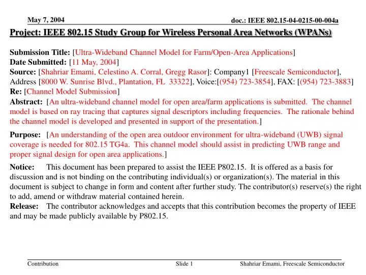
Project: IEEE 802.15 Study Group for Wireless Personal Area Networks (WPANs) Submission Title: [ Ultra-Wideband Channel Model for Farm/Open-Area Applications ] Date Submitted: [ 11 May, 2004 ]

E N D
Project: IEEE 802.15 Study Group for Wireless Personal Area Networks (WPANs) Submission Title: [Ultra-Wideband Channel Model for Farm/Open-Area Applications] Date Submitted:[11 May, 2004] Source: [Shahriar Emami, Celestino A. Corral, Gregg Rasor]: Company1 [Freescale Semiconductor], Address [8000 W. Sunrise Blvd., Plantation, FL 33322], Voice:[(954) 723-3854], FAX: [(954) 723-3883] Re: [Channel Model Submission] Abstract: [An ultra-wideband channel model for open area/farm applications is submitted. The channel model is based on ray tracing that captures signal descriptors including frequencies. The rationale behind the channel model is developed and presented in support of the presentation.] Purpose: [An understanding of the open area outdoor environment for ultra-wideband (UWB) signal coverage is needed for 802.15 TG4a. This channel model should assist in predicting UWB range and proper signal design for open area applications.] Notice: This document has been prepared to assist the IEEE P802.15. It is offered as a basis for discussion and is not binding on the contributing individual(s) or organization(s). The material in this document is subject to change in form and content after further study. The contributor(s) reserve(s) the right to add, amend or withdraw material contained herein. Release: The contributor acknowledges and accepts that this contribution becomes the property of IEEE and may be made publicly available by P802.15. Shahriar Emami, Freescale Semiconductor
Ultra-Wideband Channel Modelfor Farm/Open-Area Applications Understanding UWB Propagation in Open Areas Subject to Selected Environmental Factors Shahriar Emami, Celestino A. Corral, Gregg Rasor Freescale Semiconductor The presenters wish to acknowledge the support and contributions of: • Glafkos Stratis/Motorola • Salvador Sibecas/Motorola Shahriar Emami, Freescale Semiconductor
Outline • Ultra-wideband Outdoor Channel Model Status • Special Considerations • Approach • Frequency Selection • Simulation Setup • Simulation Results • Ground conditions • Channel Impulse Response and Ray Statistics • Coverage • Summary and Conclusions • Proposed Continuing Investigations Shahriar Emami, Freescale Semiconductor
Channel Model Status We shall show this in simulation • Prior Efforts: • Two-ray UWB path loss model: • S. Sato and T. Kobayashi, “Path-loss exponents of ultra wideband signals in line-of-sight environments,” IEEE802.15-04-0111-00-004a, March 2004. • Deterministic UWB channel model based on ray tracing approach: • B. Uguen, E. Plouhinec, Y. Lostanlen, and G. Chassay, “A deterministic ultra wideband channel modeling,” 2002 IEEE Conf. Ultra Wideband Syst. Tech. We use approach considered here Shahriar Emami, Freescale Semiconductor
Special Considerations • Farm areas feature isolated clusters of scatterers • Material properties may change with frequency. (For our simulations, we assume material properties constant over frequency.) In addition, the outdoor channel is subject to environmental changes • Seasonal changes (snow, ice, etc. in some regions) • Rain/wet conditions Shahriar Emami, Freescale Semiconductor
Different Absorption Regions Frequency Range Of Interest Conduction Dipole and Ionic Relaxation We assume no dielectric changes over frequency Space Charge Polarization Atomic Electronic Absorption -6 -4 -2 0 2 4 6 8 10 12 14 16 18 Log frequency (Hz) 60Hz Dielectric practically constant over frequency range of interest. R. C. Dorf (Ed.), The Electrical Engineering Handbook, 2nd Ed., Boca Raton, Florida: CRC Press, 1997. Shahriar Emami, Freescale Semiconductor
Approach • Use deterministic 3-D ray tracing simulator - Employs • geometric optics • uniform theory of diffraction (UTD) • Generates • Received signal strength • Ray statistics (path length/delay) • Signal descriptors include frequency, polarization, etc. • UWB channel sounding is achieved by superposition of NB channel sounding - Conventional channel sounding - FCC emissions mask scaled channel sounding M. F. Iskander and Z. Yun, “Propagation prediction models for wireless communication systems,” IEEE Trans. Microwave Theory Tech., vol. 50, pp. 662—673, March 2002. Shahriar Emami, Freescale Semiconductor
Frequency Selection Energy of band concentrated in high band frequency 0 dBm -11.2 -11.4 -12.8 -13.8 -14.8 3.10 4.24 5.34 6.72 8.64 10.6 3.10 4.24 5.34 6.72 8.64 10.6 Channel Sounding “High-Pass” Sounding Energy of band concentrated in geometric center frequency -11.2 -11.4 -12.8 -13.8 -14.8 3.62 4.76 5.99 7.62 9.57 “Band-Pass” Sounding Shahriar Emami, Freescale Semiconductor
Simulation Set-Up 3-D omni antenna pattern used Omni pattern assumed at all frequencies Provides worst-case delay modeling omni antenna above house omni antenna near ground Receiver grid placed around home, 200m X 200m Receiver spacing was 4m X 4m Receiver height was at 1.3m For omni antenna above house, antenna was at 12.5m height For omni antenna near ground, antenna was at 1.5m height. Farm area consists of two-story wood home and metal grain silo. Ground is not flat; has slight variations in height. Shahriar Emami, Freescale Semiconductor
Coverage ResultsLowest Frequency – 4.24 GHz Dry soil Wet soil and wet roof 200 m 200 m TX power = 0 dBm TX power = 0 dBm Highest level -64.4 dBm Shadowing due to metal silo evident Ripple due to two-ray phenomenon evident Highest level -66.5 dBm Smoother ripple closer to antenna Impact of roof more significant Shahriar Emami, Freescale Semiconductor
Coverage ResultsFull Frequencies -- Channel Sounding Dry soil Wet soil TX power = 0 dBm TX power = 0 dBm Highest level -64.4 dBm Some deep fades are eliminated, others softened Ripple due to two-ray phenomenon still evident, although smooth ripple closer Highest level -66.5 dBm Higher signals closer to antenna Shadowing due to silo and roof still significant Dry/wet conditions are fairly similar Shahriar Emami, Freescale Semiconductor
Coverage“High-pass” and “Band-pass” Sounding Dry soil Dry soil TX antenna placed at 1.5m height and at the side of the house High-pass sounding Highest level -61.8 dBm Significant shading by house as well as silo Band-pass sounding Highest level -60.2 dBm Range for -75 dBm sensitivity is quite low, on the order of 15 m. High-pass and band-pass sounding are similar Shahriar Emami, Freescale Semiconductor
Simulation--Validation • Powers in the different frequency bands are summed together • Received power profile in agreement with the work of Sato and Kobayashi TX antenna placed at 1.5m height and at the side of the house Shahriar Emami, Freescale Semiconductor
Simulation Results—Ground Conditions • Ground conditions (wet or dry) has almost no impact on received signal power or delay spread. • Subsequent simulations were assuming dry conditions Shahriar Emami, Freescale Semiconductor
Simulation Results—Channel Impulse Response • CIR is similar to two-ray model. Shahriar Emami, Freescale Semiconductor
Simulation Results—Channel RF Parameters Table I. 90 percentile received power Table II. 90 percentile delay spread - Scenario A: transmit antenna is placed on the top of farm house - Scenario B: transmit antenna is placed along the side of the house Shahriar Emami, Freescale Semiconductor
Statistics of the two rays are found to be Rayleigh distributed. Simulation Results—Ray Statistics Shahriar Emami, Freescale Semiconductor
Channel (uniform) sounding leads to larger received power as compared to constrained channel (FCC-mask compliant) sounding. Simulation Results—Channel Sounding FCC-mask complaint Uniform sounding Over 10dB difference Shahriar Emami, Freescale Semiconductor
“Band-pass” sounding results in +1 dB higher received power compared to “high-pass” sounding. Simulation Results—“High-pass” or “Band-pass” Sounding High-pass and band-pass sounding are similar High-pass Band-pass Shahriar Emami, Freescale Semiconductor
Simulation Results—Coverage Table III. % grid Coverage, if the receiver sensitivity is -90 dBm. Shahriar Emami, Freescale Semiconductor
Simulation Results—Channel Model * The transmitter receiver separation distances are 5, 15 and 75 meters in CM1, CM2 and CM3, respectively. Shahriar Emami, Freescale Semiconductor
Summary and Conclusions UWB Ray Tracing: • Ray tracing with realistic antennas and appropriate material properties was implemented. • Analyses included all ray statistics/parameters (ray physics). • CIR of UWB channel is found by superposition of CIR of individual bands with appropriate power weighting. Channel Modeling Results: • 5-band approach is adequate for predicting outdoor coverage in farm scenario as verified by prior two-ray modeling. • “High-pass” sounding yields most conservative results. • RF parameters appear almost insensitive to ground material/conditions. • 100m range achievable with -90dBm RX sensitivity. • CIR is similar to that of two-ray model. RMS delay depends on location of antenna and statistics of the rays. • Two-ray statistics are verified to have Rayleigh distribution. Shahriar Emami, Freescale Semiconductor
Ongoing Investigations • Incorporate uplink simulations. • Alternative frequency domain based approach. • Measurement and verification. Shahriar Emami, Freescale Semiconductor
Back-up Slides Shahriar Emami, Freescale Semiconductor
Material Properties Pellat-Debye Equations for loss at single relaxation time. Real permittivity exhibits low-pass frequency response. Imaginary part exhibits band-pass response. Regions can be separated for different relaxation times. Temperature effects are not modeled, but only affected by change in density of dielectric material. Reference Data for Engineers: Radio, Electronics, Computer & Communications, 8th Ed., Carmel, Indiana: SAMS, Prentice-Hall Computer Pub., 1993. Shahriar Emami, Freescale Semiconductor