Download
1 / 27
270 likes | 409 Views
ILC DR Working Group on Collective Effect: Electron Cloud. M. Pivi SLAC, on behalf of ILC DR Working Group 27-29 March, 2010 LCWS10 & ILC10 Beijing, China. Beam Instability simulation code. To estimate e- cloud beam instability used CMAD (M. P. SLAC), developed since 2006

E N D
ILC DR Working Group on Collective Effect: Electron Cloud M. Pivi SLAC, on behalf of ILC DR Working Group 27-29 March, 2010 LCWS10 & ILC10 Beijing, China
Beam Instability simulation code • To estimate e- cloud beam instability used CMAD (M. P. SLAC), developed since 2006 • Include full machines lattice from MAD: beta functions, dispersion, chromaticity, etc. • “Parallel” simulations up to ~100 processors, to deal with many lattice elements and turns (>1000). • Beam and cloud represented by macroparticles. Particle in cell PIC code. • 6D beam particle dynamics; 3D electron cloud dynamics in 2D forces. • e- cloud pinching and magnetic fields included.
Simulation code • CMAD: Tracking the beam (x,x’,y,y’,z,d) in a MAD lattice by 1st order and 2nd (on/off) transport maps and with electron clouds distributed in the ring. • MAD8 or X “sectormap” and “optics” files as input • Apply beam-cloud interaction point (IP) at each element in the lattice. • Benchmarking with existing codes HEAD-TAIL, WARP/POSINST: very good to excellent. • Study incoherent emittance long-term growth below threshold: “real or numerical?”
ILC DR instability simulations • CMAD a tracking and e-cloud beam instability parallel code (M.Pivi SLAC) • Taking MAD(X) optics file at input, thus tracking the beam in a real lattice and applying the interaction beam-electron cloud over the whole ring • Assumed cloud in magnetic fields and solenoids (no cloud) in drift regions • Finding: lower density thresholds for the 6km ring DC04 lattice: 6.4 km ring DSB3 lattice: 3.2 km ring 2.5e11 4.4e11 Beam losses 2.2e11 3.9e11 2.0e11 3.5e11 1.7e11 M. Pivi, SLAC
Tune shift in the 6km DR - DCO4 ILC DR instability simulations CMAD Plot the power spectrum of the beam centroid recorded at BPM location M. Pivi, SLAC
Incoherent tune shift in DCO4 DR No cloud in DCO4 ring with cloud avg 1.2e10 e/m3 with cloud avg 1.2e11 e/m3 (below instability) All combined Plotting the tunes of selected particles in the beam CMAD M. Pivi, SLAC
Comparing cloud density instability threshold with cloud density from build-up To compare with beam instability type of simulations, from the build-up simulations we extracted the cloud density defined as: • density at equilibrium after electron cloud build-up • density NEAR THE BEAM (10 sx, 10 sy) • density JUST BEFORE electron cloud pinching (head of bunch) The three conditions above satisfied at once. Next showing latest build-up simulations used for the comparison process
Bending magnet build-upspace-averaged ecloud density DC04, w/o antch. DC04, w antch. DSB3, w antch. DSB3, w/o antch.
ne at bunch front within 10 beam s’s(*)units: 1012 m–3 (*) Note: these simulated data have large errors (~30-40%) due to statistical noise. Within these errors, there is no difference between the time-averaged density and the instantaneous density at the last bunch in the train
e- cloud “distribution” - 6km ring SEY=0.9 SEY=1.2 SEY=1.4 Snapshot of the cloud distribution in dipole “just before” the passage of the last bunch for: R=25%, =90% Theo Demma, LNF
e-cloud density at bunch front within 10 beam s’s(*) units: 1012 m–3 (*) Note: these simulated data have large errors (~30-40%) due to statistical noise. Within these errors, there is no difference between the time-averaged density and the instantaneous density at the last bunch in the train Theo Demma, INFN
Ecloud in quadrupoles & sextupoles: parameters Lanfa Wang, SLAC March 23, 2010 3.2km DR 6.4km DR • Field: 7.5T/m • Length:0.3m • Pipe radius: 25mm • SEY: 0.9~1.4 • Beam Size: (270,5) m • Field: 12T/m • Length:0.3m • Pipe radius: 25mm • SEY: 0.9~1.4 • Beam Size: (360,6) m
SEY effect (3km Ring)Quadrupole: Photon Reflectivity =20%Antechamber protection =0 Average density build-up Central density build-up Lanfa Wang, SLAC
SEY effect (3km Ring)Sextupole: Photon Reflectivity =20%Antechamber protection =0 Average density build-up Central density build-up
SEY effect (3km Ring)Quadrupole: Photon Reflectivity =20%Antechamber protection =98% Note: ecloud is not saturated for large SEY Average density build-up Central density build-up
SEY effect (6km Ring)Sextupole: Photon Reflectivity =20%Antechamber protection =98% Average density build-up Central density build-up
Photoelectrons production For these set of simulations: • Analytic estimates for the synchrotron radiation with antechamber (see O. Malyshev and T. Demma presentations) • Including next: synchrotron radiation simulations with antechamber, photon reflectivity, photoelectric yield, etc. Synrad3D
Simulation input parameters for all cases(mostly from M. Pivi, 17 Nov. 2009 et. seq.) (*) This means that 10% of the photoelectrons are generated localized at the right “edge” of the chamber, whether or not there is an antechamber (probably not realistic, but probably not very important for high values of R)
Build Up Parameters for DC04 & DSB3 *https://wiki.lepp.cornell.edu/ilc/pub/Public/DampingRings/WebHome/DampingRingsFillPatterns.xls Theo Demma, INFN
Build Up Input Parameters for CLOUDLAND ilc-DR 6.4 Km, 6 ns bunch spacing*. *https://wiki.lepp.cornell.edu/ilc/pub/Public/DampingRings/WebHome/DampingRingsFillPatterns.xls
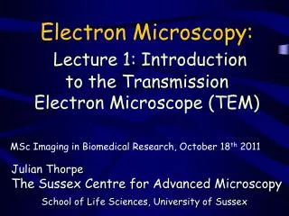
Compare thresholds for 6 km and 3km DR SEY 1.4 SEY 1.2 antechamber antechamber Simulation Campaign 2010: compiled data of build-up simulations compared with the simulated beam instability thresholds. Overall ring average cloud densities are shown for the 6 km and 3 km rings. The surface Secondary Electron Yield (SEY) determines the cloud build-up and density level. S. Guiducci, M. Palmer, M. Pivi, J. Urakawa on behalf of the ILC DR Working Group
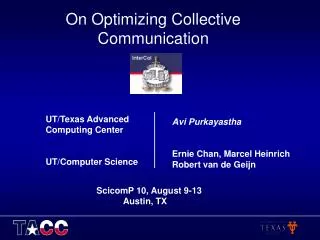
Compare thresholds for 6 km and 3km DR SEY 1.4 SEY 1.2 SEY 1.1 SEY 0.9 Complete set of data. All simulations for antechamber eta=97-98%, but R=0.2 and R=0.9. Compiled data from build-up simulations and compare against and beam instability thresholds. Showing the overall ring average cloud density for the 6 km and 3km rings
Statistical errors and parameters variation Will be refined by SR simulations • Errors in the cloud density near beam 30-40% due to statistical noise • Lower cloud density when reflectivity R=0.2 instead of R=0.9 • Factor ~4-5 increase in cloud density if antechamber protection is h=90% (instead of h=98%). What is our level of confidence on h=98%? These may set a lower threshold for the acceptable SEY
Summary of Working Group findings • Given the same current and bunch distance we expect similar or even higher instability threshold for the shorter ring • Need for antechamber designs either in 6km and 3km DR • With an antechamber design and train gaps, a SEY 1.1-1.2 offer sufficient margin against beam instability. Need to factor in parameters variation and statistical errors.
Recommendation and Risks Assessment With respect to the RDR baseline, the risk level for adopting a reduced 3km Damping Ring while maintaining the same bunch spacing is: Low. The acceptable surface Secondary Electron Yield (SEY) may strongly depend on issues not yet thoroughly investigated such as beam jitter and slow incoherent emittance growth. Refined estimations of the photoelectron production rate by simulations will better define the maximum acceptable SEY. S. Guiducci, M. Palmer, M. Pivi, J. Urakawa on behalf of the ILC DR Working Group
(Cont’) Recommendation and Risks Assessment • Reducing the positron ring circumference to 3-km eliminates the back up option of 12 ns bunch spacing (safer e- cloud regime) and may reduce the luminosity margins. • In the event that effective EC mitigations cannot be devised for a 3km damping ring, an option of last resort would be to add a second positron damping ring. S. Guiducci, M. Palmer, M. Pivi, J. Urakawa on behalf of the ILC DR Working Group