Download
1 / 5
50 likes | 58 Views
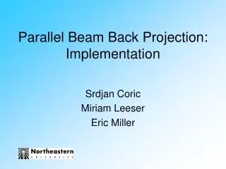
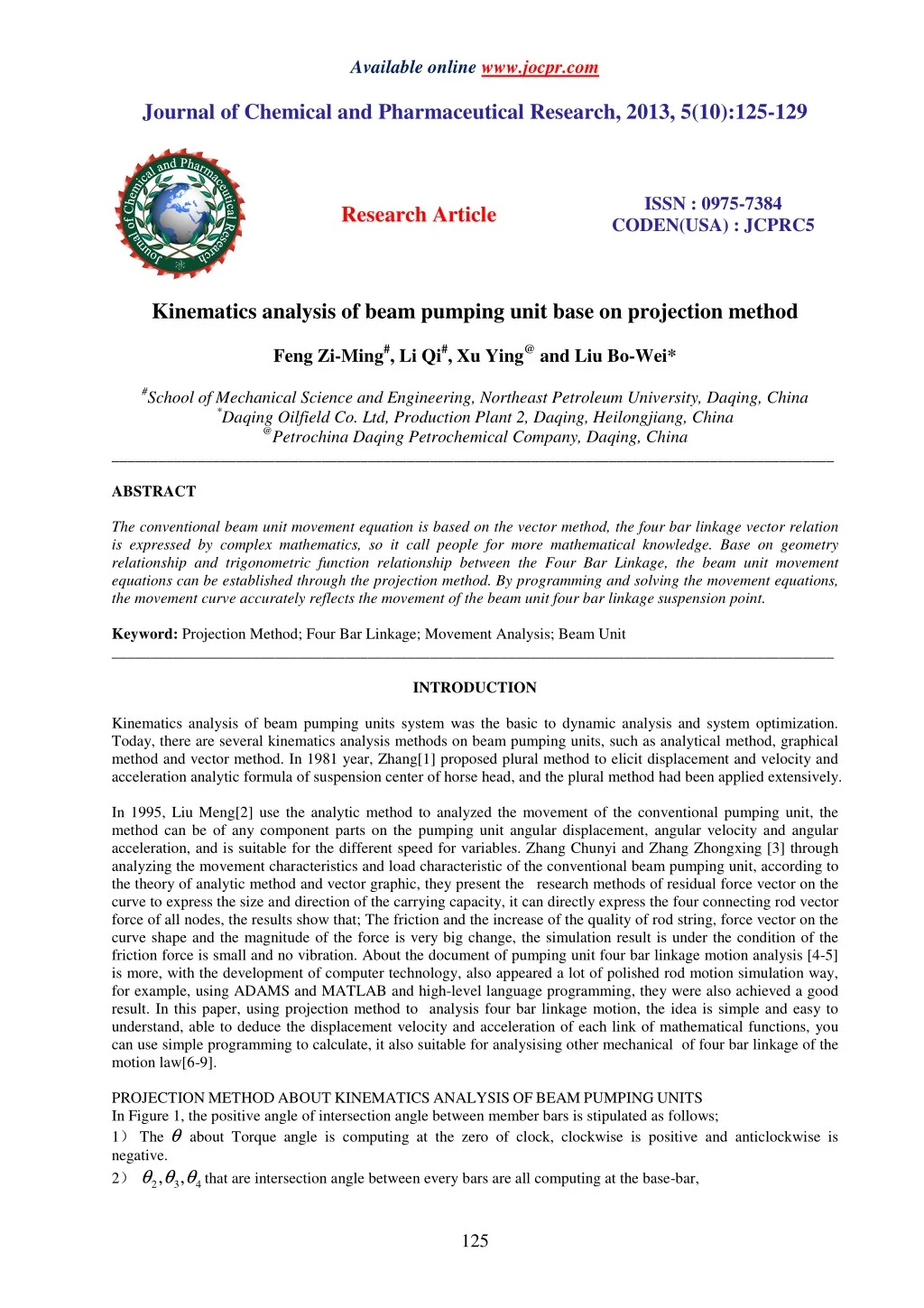
The conventional beam unit movement equation is based on the vector method, the four bar linkage vector relation<br>is expressed by complex mathematics, so it call people for more mathematical knowledge. Base on geometry<br>relationship and trigonometric function relationship between the Four Bar Linkage, the beam unit movement<br>equations can be established through the projection method. By programming and solving the movement equations,<br>the movement curve accurately reflects the movement of the beam unit four bar linkage suspension point. <br>

E N D
Available online www.jocpr.com Journal of Chemical and Pharmaceutical Research, 2013, 5(10):125-129 ISSN : 0975-7384 CODEN(USA) : JCPRC5 Research Article Kinematics analysis of beam pumping unit base on projection method Feng Zi-Ming#, Li Qi#, Xu Ying@ and Liu Bo-Wei* #School of Mechanical Science and Engineering, Northeast Petroleum University, Daqing, China *Daqing Oilfield Co. Ltd, Production Plant 2, Daqing, Heilongjiang, China @Petrochina Daqing Petrochemical Company, Daqing, China _____________________________________________________________________________________________ ABSTRACT The conventional beam unit movement equation is based on the vector method, the four bar linkage vector relation is expressed by complex mathematics, so it call people for more mathematical knowledge. Base on geometry relationship and trigonometric function relationship between the Four Bar Linkage, the beam unit movement equations can be established through the projection method. By programming and solving the movement equations, the movement curve accurately reflects the movement of the beam unit four bar linkage suspension point. Keyword:Projection Method; Four Bar Linkage; Movement Analysis; Beam Unit _____________________________________________________________________________________________ INTRODUCTION Kinematics analysis of beam pumping units system was the basic to dynamic analysis and system optimization. Today, there are several kinematics analysis methods on beam pumping units, such as analytical method, graphical method and vector method. In 1981 year, Zhang[1] proposed plural method to elicit displacement and velocity and acceleration analytic formula of suspension center of horse head, and the plural method had been applied extensively. In 1995, Liu Meng[2] use the analytic method to analyzed the movement of the conventional pumping unit, the method can be of any component parts on the pumping unit angular displacement, angular velocity and angular acceleration, and is suitable for the different speed for variables. Zhang Chunyi and Zhang Zhongxing [3] through analyzing the movement characteristics and load characteristic of the conventional beam pumping unit, according to the theory of analytic method and vector graphic, they present the research methods of residual force vector on the curve to express the size and direction of the carrying capacity, it can directly express the four connecting rod vector force of all nodes, the results show that; The friction and the increase of the quality of rod string, force vector on the curve shape and the magnitude of the force is very big change, the simulation result is under the condition of the friction force is small and no vibration. About the document of pumping unit four bar linkage motion analysis [4-5] is more, with the development of computer technology, also appeared a lot of polished rod motion simulation way, for example, using ADAMS and MATLAB and high-level language programming, they were also achieved a good result. In this paper, using projection method to analysis four bar linkage motion, the idea is simple and easy to understand, able to deduce the displacement velocity and acceleration of each link of mathematical functions, you can use simple programming to calculate, it also suitable for analysising other mechanical of four bar linkage of the motion law[6-9]. PROJECTIONMETHODABOUTKINEMATICSANALYSISOFBEAMPUMPINGUNITS In Figure 1, the positive angle of intersection angle between member bars is stipulated as follows; 1)The θ about Torque angle is computing at the zero of clock, clockwise is positive and anticlockwise is negative. 2) 2 3 4 , , θ θ θ that are intersection angle between every bars are all computing at the base-bar, 125
Liu Bo-Wei et al ______________________________________________________________________________ J. Chem. Pharm. Res., 2013, 5(10):125-129 3) Every intersection bar of four-bar linkage is stipulated as follows; L1-base bar length of beam pumping units; L2-crank radius of beam pumping units; L3-connecting rod length of beam pumping units; L4-length of back-walking beam L5-length of fore-walking beam The equation set is established due to the geometrical relationship in the Figure 2; cos( ) cos( ) cos( sin( ) sin( ) sin( ) L L L θ θ θ + − θ + θ − θ − θ = ) − cos( ) θ 0 L L L L 2 2 3 3 4 4 1 sin( ) 1 (1) = 0 L 2 2 3 3 4 4 1 1 θ = 1θ is the intersection angle between base bar and base bar, so 0 Because following equations; , formula (1) can be simplified into the 1 θ θ + + θ − θ − = cos( sin( ) cos( ) sin( ) θ cos( ) = 0 L L L L L L 2 2 3 3 4 sin( 4 ) 1 (2) − θ ) 0 L 2 2 3 3 4 4 It is very tedious to solve the system of equations (2) using algebraic method, the formula (3) are implicit function about 3 4 , θ θ , it is not complex to program and compute it. 2 sin( )sin( ) 2 arccos 2 cos( ) 2 L L L L θ − − − − + = − Angle velocity of every rod piece can be achieved by the geometrical relationship shown in figure 1, θ is angle velocity of crank, 2 α =0, 2 α is angle acceleration of crank. sin( ) sin( ) sin( ) sin( ) L θ θ − − − − − θ θ + θ 2 4 2 1 2 2 2 3 cos( ) L L L L L L L L θ = 2 3 2 3 1 2 2 3 2 3 2 θ 1 3 (3) θ + θ 2 3 2 1 2 4 2 2 2 L L sin( 2 L L )sin( ) cos( ) θ 2 cos( ) L L L L L L L L θ arccos 2 4 2 4 1 2 2 4 2 1 4 2 4 2 ω = − ω , 2 − ω θ θ θ L = ω 2 L ω 2 4 − 2 3 θ − 2 3 θ 4 θ (4) L = ω 2 2 2 3 4 4 4 3 Angle acceleration of every can be achieved with derivation of formula set (4); 2 2 2 4 2 2 2 3 3 sin( ) cos( sin( L − θ − θ + ω θ − θ − + ω θ − θ − ω 2 3 2 4 sin( ) cos( L ) cos( ) a L L L L = 4 θ θ θ 2 θ + 3 4 3 4 a sin( θ ) 3 4 (5) θ − θ − ω − ω θ − θ − ω 2 2 2 4 2 3 ) θ cos( ) a L L L L = 2 2 3 2 2 3 2 4 3 4 3 a 4 − ) 4 3 4 a = − 0 Because the angle acceleration of crank is shown as ω θ θ − = − − = ,formula (5) can be simplified as follow; 2 L + ω θ − θ ω 2 2 2 3 2 4 cos( ) cos( θ − ) L L 2 4 2 L θ 3 θ 4 3 4 a 3 sin( + ) 3 3 ω θ 4 (6) ω θ θ − θ − ω 2 2 2 4 − 2 3 cos( ) cos( θ ) L L L 2 3 2 4 3 4 3 a 4 sin( ) L 4 3 4 126
Liu Bo-Wei et al ______________________________________________________________________________ J. Chem. Pharm. Res., 2013, 5(10):125-129 Line velocity of every bar piece is; sin( sin( θ − θ − θ θ ) ) = 2 3 V V (7) 4 2 4 3 When the horse head suspension center is located at the center extreme of up and down dead position, the minimum and maximum intersection angles min ψ 、 max ψ , between pumping unit base bar and back walking beam, is respectively; 2 2 2 1 4 3 2 min 1 4 2 2 2 1 4 3 2 max 1 4 2 L L + − − ( ) L L L L ψ = arccos( ) 2 L L − (8) + + ( ) L L L L ψ = arccos( ) Stroke length S of Suspension center is; ( ) S ψ ψ = − L (9) max min 5 The zero suspension displacement is taken as down dead center, the up moving direction of polish rod is taken as the positive direction, so suspension center’s instant displacement ( ) L ψ ψ = − (10) c S is; cS max 5 ψ - intersection angle of back walking beam and base bar at arbitrary time. The tilt angle between ground rocking bar and base bar is 2 2 3 1 4 max 3 1 2 ( arccos( 2 L L + − + 2 ( ) L L L L ϕ = arccos( ) 2 L L − (11) + − 2 2 2 ) L L L L ϕ = ) 3 1 4 2 min 3 1 θ4 ω4 L4 L5 L3 V4 ω3 θ3 V2 θ2 V3 ω2 L2 Figure 1 structural diagram of four-bar linkage of beam pumping units 127
Liu Bo-Wei et al ______________________________________________________________________________ J. Chem. Pharm. Res., 2013, 5(10):125-129 CASECOMPUTATION Four bar linkage kinematic characteristic above this paper is taken as theoretical basis, the traditional walking beam pumping unit kinematic simulation can be achieved with iterative computations program. CYJ3-1.5-6.5HB type pumping unit is taken as case, all the length of four bar linkage can be achieved by referring the relative handbook, then the kinematic function, about walking beam pumping unit, is founded. The figure 2 to figure 5 are showing the displacement curve and velocity curve and acceleration curve against to crank angle using the above formula. CYJ3--1.5--6.5HB 2 Displacement 1 0 0 20 40 60 80 100 120 140 160 180 200 220 240 260 280 300 320 340 360 Torsion Angle Figure 2 Displacement curve CYJ3--1.5--6.5HB 0.35 0.3 0.25 0.2 0.15 0.1 0.05 Velocity 0 -0.05 -0.1 -0.15 -0.2 -0.25 -0.3 -0.35 -0.4 0 20 40 60 80 100 120 140 160 180 200 220 240 260 280 300 320 340 360 Torsion Angle Figure 3 Velocity curve CYJ3--1.5--6.5HB 0.45 0.4 0.35 0.3 0.25 0.2 0.15 Acceleration 0.1 0.05 0 -0.05 -0.1 -0.15 -0.2 -0.25 -0.3 -0.35 -0.4 0 20 40 60 80 100 120 140 160 180 200 220 240 260 280 300 320 340 360 Torsion Angle Figure 4 Acceleration curve CONCLUSION The kinematic equation of displacement, velocity and acceleration of walking beam unit is achieved by geometric projection method. The derived suspension center kinematic function in this paper is taken as simulation mathematic model, and the pumping unit kinematic simulation software is programed with VB6.0. At last, the CYJ3-1.5-6.5HB type pumping unit is selected as computed case, and the suspension displacement, velocity and acceleration of 128
Liu Bo-Wei et al ______________________________________________________________________________ J. Chem. Pharm. Res., 2013, 5(10):125-129 pumping unit are computed and form relative curve. Comparing to the other kinematic analysis methods of four bar linkage, the geometric projection method in this paper has achieved the same conclusion. Acknowledgement The authors gratefully acknowledge the projects’ support of National Key Technology Support Program of China (Contract No.2011BAA02B00-01) and the Science and 2014 Year Technology Research Project of Heilongjiang Province Education Department (Name: Beam Pumping Unit and Motor Coupling Operation and Reasonable Matching Theory Research). REFERENCES [1]SN Zhang, Daqing Pereoleum Institute Journal, 1981,3(4),40-60 [2]M Liu, Xinjiang Petroleum Technology, 1995,1(5),91-93 [3]CY Zhang; XZ Zhang, Petroleum Machine, 2003v,31(8),6-19 [4]YM Wu; XG Liu; XQ Wang, Petroleum and Oil Field Machine, 2006,35(5), 75-77 [5]MQ Xiao; Q Zhang; JL Yu, Petroleum and Oil Field Machine, 2009, 38(12),49-52 [6]J, Sujeet, J. Chem. Pharm. Res. , 2013,5(4),1-3 [7]A Kiran; TM Kumar; N Raghunandan; A Shilpa, J. Chem. Pharm. Res.,2012,4(5),2580-2584 [8]G, Ngangom; DK Pramodini; ST Imoba, J. Chem. Pharm. Res., 2013,5(2),78-51 [9]AP Rajput; MC Sonanis, J. Chem. Pharm. Res., 2012,4(9),4127-4133 129