Download
1 / 10
100 likes | 127 Views
Gears. Gear Basics. Types of Gears. Spur Gear. Spur Gear. Ring Gear (Internal). Racks. Types of Gears. Straight Bevel Gears. Miter Gear. Spiral Bevel Gears. Worm Gear. Gear Terminology. Basic Gear Design.

E N D
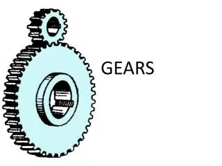
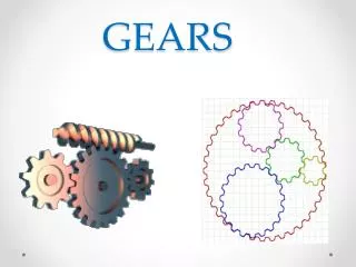
Gears Gear Basics
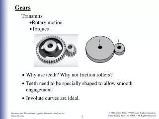
Types of Gears Spur Gear Spur Gear Ring Gear (Internal) Racks
Types of Gears Straight Bevel Gears Miter Gear Spiral Bevel Gears Worm Gear
Basic Gear Design Commercially available gears are specified on drawings and are used whenever possible. Stock gears are available in a wide range of forms and sizes. Gear design includes the selection of the gear sizes, pitch diameter, center to center distance, size and form of the teeth, shaft diameter, horsepower rating, speed rations, and appropriate heat treatment and materials. In actual practice, the designer provides the detail drafter with only a few basic dimensions of the required gears. The designer may obtain this data from actual engineering calculations or from manufacturer's catalogs. All other dimensions needed in the construction of the working drawings are usually worked out by the detail drafter.
Basic Gear Design CENTER TO CENTER DISTANCES OF TWO FRICTION WHEELS
Basic Gear Design CENTER TO CENTER DISTANCES OF TWO GEARS
Basic Gear Design Diametral Pitch (P) The diametral pitch (P) is a ratio equal to the number of teeth (N) on the gear per inch of pitch diameter (D). Diametral Pitch (P) = Number of Teeth (N)/ Pitch Diameter (D) Number of teeth (N) The number of teeth (N) is the number of gear teeth on the gear or pinion. Number of teeth (N) = Diametral Pitch (P) x Pitch Diameter (D) Pitch Diameter (D) The pitch diameter (D) is an imaginary circle that corresponds to the circumference of the friction gear from which the spur gear is derived. Pitch Diameter (D) = Number of teeth (N)/ Pitch Diameter (P) Center to Center Distance (C to C) The center to center distance (C to C) is the distance between the centers of the two friction wheels C to C = (Pitch Diameter of Gear (D1) + Pitch Diameter of Pinion (D2))/2 C to C = ((D1) + (D2))/2
Basic Gear Design Gear Ratio (M) When two friction wheels of different diameter are placed together a point of the driver gear will travel the same distance as a point of the driven gear. Therefore, the number of teeth and the speed of the gears are directly proportional to its pitch diameter. M1 = D1 = N1 = RPM2 M2 D2 N2 RPM1 Linear Velocity (V) Linear velocity is the distance that a given point on the friction wheel travels during a certain time period. Linear Velocity (V) = (pi) x Pitch Diameter of Gear (D) x RPM
Basic Gear Design Sample Problem: Complete the missing information on the gear train problem. M(A) = 2 M(B) = 1 M(C) = 3 M(D) = 2