Download
1 / 3
50 likes | 155 Views
GIC India is a manufactures, suppliers of devices for Earth Leakage Relays, Smart Relays and Motor Protection Relays to give your equipment an added layer of safety. http://gicindia.com/products/earth-leakage-relay.html

E N D
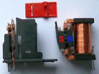
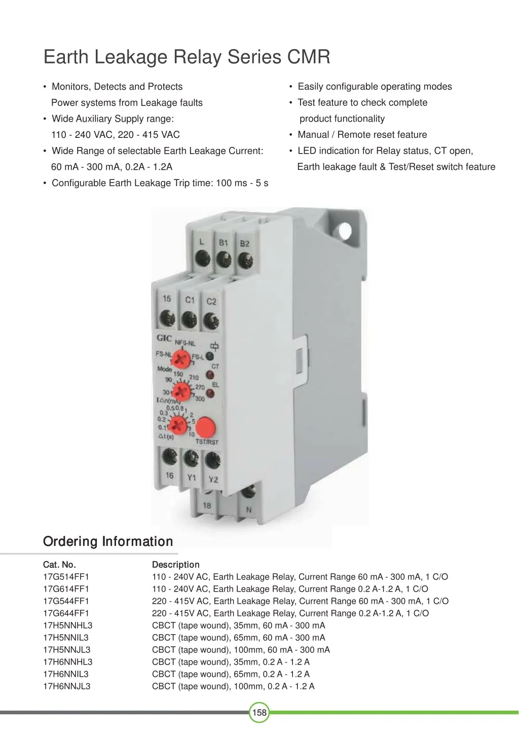
Earth Leakage Relay Series CMR • Easily configurable operating modes • Monitors, Detects and Protects • Test feature to check complete Power systems from Leakage faults product functionality • Wide Auxiliary Supply range: • Manual / Remote reset feature 110 - 240 VAC, 220 - 415 VAC • LED indication for Relay status, CT open, • Wide Range of selectable Earth Leakage Current: Earth leakage fault & Test/Reset switch feature 60 mA - 300 mA, 0.2A - 1.2A • Configurable Earth Leakage Trip time: 100 ms - 5 s Ordering Information Ordering Information Cat. No. Cat. No. 17G514FF1 17G614FF1 17G544FF1 17G644FF1 17H5NNHL3 17H5NNIL3 17H5NNJL3 17H6NNHL3 17H6NNIL3 17H6NNJL3 Description Description 110 - 240V AC, Earth Leakage Relay, Current Range 60 mA - 300 mA, 1 C/O 110 - 240V AC, Earth Leakage Relay, Current Range 0.2 A-1.2 A, 1 C/O 220 - 415V AC, Earth Leakage Relay, Current Range 60 mA - 300 mA, 1 C/O 220 - 415V AC, Earth Leakage Relay, Current Range 0.2 A-1.2 A, 1 C/O CBCT (tape wound), 35mm, 60 mA - 300 mA CBCT (tape wound), 65mm, 60 mA - 300 mA CBCT (tape wound), 100mm, 60 mA - 300 mA CBCT (tape wound), 35mm, 0.2 A - 1.2 A CBCT (tape wound), 65mm, 0.2 A - 1.2 A CBCT (tape wound), 100mm, 0.2 A - 1.2 A 158 158
Earth Leakage Relay Series CMR Cat. No. Cat. No. Parameters Parameters Supply Voltage ( ) Supply Variation Frequency 17G514FF1 17G514FF1 17G614FF1 17G614FF1 17G544FF1 17G544FF1 17G644FF1 17G644FF1 110 - 240 VAC -20 to +10% 220 - 415 VAC 50/60Hz 5 VA 60 mA to 300 mA Fail Safe Latch (FSL), Fail Safe Non Latch (FSNL), Non Fail Safe Non Latch (NFSNL) 10 VA 60 mA to 300 mA Power Consumption (Max.) Leakage Current Range Mode 0.2 A to 1.2 A 0.2 A to 1.2 A 0.1 - 0.2 - 0.4 - 2 - 5 100 ms (Irrespective of the Set Trip Time) Trip Time ( t in sec) Trip Time ( For 5 In) Local & Remote (For Fail Safe Latch mode only) Below 85% of Current sensitivity level and in presence of CBCT Test / Reset Reset Enabled Reset Time ON Delay Setting Accuracy Repeat Accuracy < 100 ms 50 ms ( -10% (85ms to 100 ms trip time for 100 ms setting in NFSL) ± 2% 1 C/O ± 20 ms ) Relay Output Contact Rating Electrical Life Mechanical Life 5A (Resistive) @ 240 VAC / 30 VDC Output 5 1 x 10 1 x 10 7 Rated Voltage (Ue): 120/240 V, Rated Current (Ie): 3.0/1.5 A Rated Voltage (Ue): 24/125/250 V, Rated Current (Ie): 2.0/0.22/0.1 A Green LED (ON) Red LED: ON CT Open, Blink AC - 15 DC - 13 Utilization Category Power ON CT Open / SW Short TST / RST Switch short LED Indication Earth Leakage Red LED: ON Operating Temperature Storage Temperature o o - 15 C to +60 C o - 20 C to +80 C o Humidity (Non Condensing) Enclosure Dimension (W x H x D) (in mm) Weight (unpacked) Mounting 95% (Rh) Flame Retardant UL 4V0 22.5 X 1 83 X 00 5 11 g 0 Base / DIN rail 9 . Certification RoHS Compliant Degree of Protection P 20 for Termi als, P 40 for Enclosure I n I EMI / EMC EMI / EMC Harmonic Current Emissions ESD Radiated Susceptibility Electrical Fast Transients Surges Conducted Susceptibility Voltage Dips & Interruptions (AC) IEC 61000-4-11 Conducted Emission Radiated Emission IEC 61000-3-2 IEC 61000-4-2 IEC 61000-4-3 IEC 61000-4-4 IEC 61000-4-5 IEC 61000-4-6 CISPR 14-1 CISPR 14-1 Environmental Environmental Cold Heat Dry Heat Vibration Repetitive Shock Non-Repetitive Shock IEC 60068-2-1 IEC 60068-2-2 IEC 60068-2-6 IEC 60068-2-27 IEC 60068-2-27 ULApproval for Cat. Nos. 17G514FF1 & 17G614FF1 only. 159 159
Earth Leakage Relay Series CMR CONNECTION DIAGRAM CONNECTION DIAGRAM 2) EARTH LEAKAGE RELAY WITH CONTACTOR FAIL SAFE LATCH MODE 1) EARTH LEAKAGE RELAY WITH CONTACTOR FAILSAFE NON LATCH MODE N N L1 L1 L2 L2 L3 L3 A1 A1 M CONTACTOR CONTACTOR A2 A2 A1 A1 L1 L1 L2 L2 M M N N L1 L1 15 15 A2 A2 START START N N 16 16 L1 L1 15 15 ELR ELR 16 16 18 18 STOP STOP 1 1 2 2 18 18 CBCT CBCT B1 B1 B1 B1 Ma Ma B2 B2 B2 B2 C1 C1 C1 C1 C2 C2 C2 C2 Y1 Y1 Y2 Y2 TRT/RST TRT/RST 3) EARTH LEAKAGE RELAY WITH MCCB AND SHUNT TRIP COIL NON FAIL SAFE NON LATCH MODE 4) EARTH LEAKAGE RELAY WITH MCCB & UNDER VOLTAGE TRIP COIL FAIL SAFE LATCH MODE 5) EARTH LEAKAGE RELAY WITH MCCB & UNDER VOLTAGE TRIP COIL FAIL SAFE NON-LATCH MODE L3 N L3 N L1 L1 L2 L2 L1 L1 N N L2 L2 L3 L3 ER REAK RE K R RE K R T B UI A E A E A1 A1 L1 L1 L2 L2 L1 L1 L2 L2 A1 A1 B C RCUIT MX MX T B UI C RC MN MN A2 A2 Lm Lm 15 15 L1 L1 C RC I I A2 A2 ELR ELR 15 15 I L1 L1 16 16 N N ELR ELR 16 16 18 18 CBCT CBCT 18 18 B1 B2 C1 B1 B2 C1 C2 C2 B1 B2 C1 C2 C2 B1 B2 C1 CBCT CBCT B1 B1 B1 B1 B2 B2 B2 B2 C1 C1 C1 C1 C2 C2 C2 C2 TST/RST TST/RST Y1 Y1 Y2 Y2 TST/RST TST/RST MOUNTING DIMENSION (mm) MOUNTING DIMENSION (mm) 100.50 78.26 22.5 4.30 83.00 57.00 35.00 62.50 60.00 10.0 12.5 TERMINAL TORQUE & CAPACITY TERMINAL TORQUE & CAPACITY Torque - 0.6 N.m (5.3 Lb.in) Terminal screw - M3 Ø 3.5...4.0 mm 2 Solid Wire - 1 X 1...6 mm AWG 1 X 20 to 12 160 160