Download

1 / 43
430 likes | 531 Views
Frame - Relay. Semester 4 – chapter 6. Frame Relay Technology. What is a Frame – Relay ?. Introduction :. Circuit – switched services (T1):. Physical circuit must be established in advance between nodes (resources must be reserved).

E N D
Frame - Relay Semester 4 – chapter 6
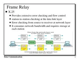
What is a Frame – Relay ? Introduction: • Circuit – switched services (T1): • Physical circuit must be established in advance between nodes (resources must be reserved). • Resources are dedicated for each connection (bandwidth is not shared).
In case of using leased lines (T1), a physical router interface is required for each destination node. • Frame-Relay (Packet – switched service): • Uses Virtual Circuits (VC) for data transmission (connection-oriented). • Bandwidth can be shared by different sources. • Path is predetermined and well known for each destination.
Only one physical interface is required on each router. • Frame-relay operates at the data-link and physical layers of OSI model. • Frame –Relay • doesn't support • error correction.
Frame-Relay Terminology: -Access rate-- It is the rate at which data travels into or out of the network. • Data-link connection identifier (DLCI)- • DLCIis a number that identifies the VC between the end device and the switch. DLCI has local significance.
LMI: • Is a signaling standard between the frame relay switch and CPE. • Responsible for keepalive messages between the switch and CPE. • Ability to give DLCI global significance. • Keeps track of DLCIs status.
Three types of LMIs are supported: • cisco • ansi • q933a • and routers need to be told which LMI type is being used (In IOS 11.2 LMI is auto sensed).
Committed information rate (CIR): The CIR is the guaranteed rate, in bits per second, that the service provider commits to providing. • Committed Burst The maximum number of bits that the switch agrees to transfer during a time interval.
Excess Burst: The maximum number of uncommitted bits that the Frame Relay switch attempts to transfer beyond the CIR. • Forward Explicit Congestion Notification (FECN): FECN is sent to the destination device, indicating that congestion has occurred.
Backward Explicit Congestion Notification (BECN): A bit set in a frame that notifies a source router that a congestion has occurred.
Discard Eligibility Indicator (DE): • A set bit that indicates the frame may be discarded in preference to other frames if congestion occurs. (DE: Set with Excess Burst traffic).
Frame-Relay DLCIs: • Frame – Relay uses PVCs (logical circuits) to identify connections with destination nodes. • Each VC is identified by a DLCI number. • A table mapping is constructed by administrator within each switch to identify the incoming / outgoing ports and associated DLCIs numbers.
X DLCI 200 Y DLCI 100 P4 P1 DLCI 110 DLCI 500 DLCI 300 B P2 DLCI 600 P0 DLCI 700 A Switch A Z P4 Switch B DLCI 400 In-DLCI Out-DLCI In-port out-port In-DLCI Out-DLCI In-port out-port P0 100 P2 110 P4 110 P1 200 P0 300 P4 400 P1 500 P4 600 P2 600 P4 700
DLCI address space is 10 digits • Possible DLCI addresses is 1024. • Usable portion of these addresses depends on the LMI type: • Cisco LMI type uses DLCI addresses from16to1007for user data • ANSI LMI type supports the range of address from16 – 992to carry user data.
Frame-Relay frame format: • Flag: the start and end of the frame. • Address field: 2 bytes, • Data field: variable • DLCI: 10 digits • FECN: 1 bit • BECN: 1 bit. • DE: 1 bit.
LMI functions: • To determine the operational status of the PVCs that the router knows about. • To transmit keepalive messages to ensure that the PVCs stays up and doesn’t shut down. • To tell the router about the active PVCs. • LMI types: • cisco • ansi • Q 933a
Global addressing: • One of the most important features of LMI options is global addressing. • It uses different DLCI values on each end of the connection.
DLCIs are locally significant, needs to be unique only on the same interface. • Global addressing makes DLCIs resemble the MAC address. • DLCI is assigned to the DTE not to the access link and must be unique. • Global address for one DTE means that all DTEs with VC to this one DTE use its global address on their access links.
With normal addressing, a static maps of destination IP address to corresponding DLCI, must be created.
40 42 40 42 50 22 50 22
200 42 50 200 200
Multicasting and Inverse ARP: • The IARP allows the router to automatically build the frame relay map. • The router learns the active DLCIs from the switch during the initial LMI exchange.
The router sends an status inquiry message to the switch, which replies with active DLCIs. • The router then sends an IARP to each DLCI for each protocol configured on the interface. • The returned information is used to build the frame relay map.
Frame – Relay mapping: • The router from the routing table determines the next hop address. • The next hop address then resolved to DLCI from map table.
What are frame-rlay subinterfaces: • Subinterfaces are logical subdivisions of a physical interface. • Early implementation of Frame Relay required that a router has a WAN serial interface for every PVC. • A single router interface can service many remote locations through individual unique subinterfaces
Configuration of subinterfaces: • Point – to – point , and • Multipoint configuration.
Point–to–point configuration: • Most widely used with spoke and partially meshed frame – relay topologies. • A single subinterface is used to establish one PVC to another physical interface or subinterface on a remote router. • Each point-point connection has its own subnet. • Each interface/subinterface would have a single DLCI. • Routing updates are not subject to split horizon.
A S0 S1 S0 C B S0.2 192.20.30.1 DLCI 40 DLCI 50 S0.1 192.20.20.1 DLCI 41 192.20.30.2 192.20.20.2 DLCI 51
A S1 S0 C B (config-if)# encaps frame-relay (Config)# interface s0.1 point-to-point (Config-if)# ip address 192.20.20.1 255.255.255.0 (Config-if)# frame-relay interface-dlci 40 (Config)# interface s0.2point-to-point (Config-if)# ip address 192.20.30.1 255.255.255.0 S0.1 DLCI 40 S0.2 192.20.20.1 DLCI 50 (Config-if)# frame-relay interface-dlci 50 -IARP is not required -LMI – is auto sensed in IOS 11.2 & later.
Multipoint configuration • May be used with fully meshed frame-relay topology. • A single subinterface has multiple PVC to multiple physical interfaces/ subinterfaces . • All subinterfaces/ interfaces would be in the same subnet. • Routing updates are subject to split horizon.
A S0.1 C B S1.1 S0.2
A S0.1 C B S1.1 S0
A S0.1 C B S1.1 S1 (config_# Int s0 (config-if)# no ip address (config-if)# encaps frame 193.40.40.1 (config)# int s0.1 multipoint DLCI 100 (config-if)# DLCI 200 ip address 193.40.40.1 Frame-relay interface-dlci 100 Frame-relay interface-dlci 200 193.40.40.2 193.40.40.3 Frame-relay map ip 193.40.40.2 100 (If IARP not supported)
A S0.1 C B S1.1 S1 Router C (config_# Int s1 193.40.40.1 (config-if)# encaps frame DLCI 100 (config-if)# DLCI 200 ip address 193.40.40.3 Frame-relay map ip 193.40.40.1 300 (If IARP not supported) DLCI 300 193.40.40.2 193.40.40.3