Download
1 / 53
630 likes | 1.13k Views
Fire Dynamics II. Lecture # 2 Ceiling Jets & Ceiling Flames Jim Mehaffey 82.583 or CVG****. Ceiling Jets and Ceiling Flames Outline Review of models for unconfined fire plumes Models for ceiling jets (temperature & velocity) Models for response of sprinklers / heat detectors

E N D
Fire Dynamics II Lecture # 2 Ceiling Jets & Ceiling Flames Jim Mehaffey 82.583 or CVG**** Carleton University, 82.583 (CVG****), Fire Dynamics II, Winter 2003, Lecture # 2
Ceiling Jets and Ceiling Flames Outline • Review of models for unconfined fire plumes • Models for ceiling jets (temperature & velocity) • Models for response of sprinklers / heat detectors • Model for ceiling flame (flame extension) • Flames located against a wall or in a corner Carleton University, 82.583 (CVG****), Fire Dynamics II, Winter 2003, Lecture # 2
Review of Models for Unconfined Fire Plume Carleton University, 82.583 (CVG****), Fire Dynamics II, Winter 2003, Lecture # 2
Unconfined Fire Plume Comprises 3 Regimes • Persistent flame (flame is present 100% of time) 0.03 < z < 0.08 Eqn (2-1) z = height above fire source (m) = heat release rate (kW) Carleton University, 82.583 (CVG****), Fire Dynamics II, Winter 2003, Lecture # 2
Unconfined Fire Plume Comprises 3 Regimes • Intermittent flame (flame present < 100% of time) 0.08 < z < 0.20 Eqn (2-2) • Flame height = height where intermittency is 50% (Correlation - Heskestad 1983) l = 0.235 - 1.02 D Eqn (2-3) D = fuel diameter (m) Carleton University, 82.583 (CVG****), Fire Dynamics II, Winter 2003, Lecture # 2
Unconfined Fire Plume Comprises 3 Regimes • Buoyant (thermal) plume (no flame is ever present) z > 0.20 Eqn (2-4) • Assume heat is released at a virtual point source zo = 0.083 - 1.02 D Eqn (2-5) zo = height of virtual source above burning item (m) Carleton University, 82.583 (CVG****), Fire Dynamics II, Winter 2003, Lecture # 2
Buoyant Plume Model (2) • Correlations often expressed in terms of = convective heat released rate (kW) • “Radius” of the plume, b (m) b(z) = 0.195 (z- zo) Eqn (2-6) Carleton University, 82.583 (CVG****), Fire Dynamics II, Winter 2003, Lecture # 2
Buoyant Plume Model (2) • Upward axial velocity, uax (m s-1) uax(z) = 1.14 (z- zo)-1/3 Eqn (2-7) • Radial dependence of upward velocity, (m s-1) u(r,z) = uax(z) exp(-r2/b2) Eqn (2-8) Carleton University, 82.583 (CVG****), Fire Dynamics II, Winter 2003, Lecture # 2
Buoyant Plume Model (2) • Axial temperature, Tax = Tax - T (K) Tax(z) = 26 (z- zo)-5/3 Eqn (2-9) • Radial dependence of temperature, T(r, z) (K) T(r, z) = Tax(z) exp[-(1.2r)2/b2] Eqn (2-10) • Average temperature, Tave Tave(z) = 14 (z- zo)-5/3 Eqn (2-11) Carleton University, 82.583 (CVG****), Fire Dynamics II, Winter 2003, Lecture # 2
Buoyant Plume Model (2) • Total upward mass flow, (kg s-1) (z) = 0.071 (z- zo)5/3 Eqn (2-12) **************************************************************** • This is probably the simplest model available. • More complex models have been incorporated into computer models or into standards for smoke control. Carleton University, 82.583 (CVG****), Fire Dynamics II, Winter 2003, Lecture # 2
Consider a Fire Plume Confined by a Ceiling Carleton University, 82.583 (CVG****), Fire Dynamics II, Winter 2003, Lecture # 2
Unconfined Ceiling Jet • Need to model ceiling jet in order to predict time to activation of sprinklers or heat detectors • Properties of ceiling jet depend on • Rate of heat release • Diameter of fire base • Height of ceiling (above virtual source) • Models are available (Fire Dynamics I) to predict • Max. temperature as a function of radial distance • Maximum velocity as a function of radial distance • Time to activation of sprinklers or heat detectors if they are subjected to max. temp & velocity Carleton University, 82.583 (CVG****), Fire Dynamics II, Winter 2003, Lecture # 2
Fire Plume Confined by Ceiling Experiments - Alpert 1972 • unconfined smooth ceiling • buoyant plume impinges on ceiling • steady fires / no hot layer • variety of fuel packages • heat release rate: 668 kW 98 MW • ceiling height 4.6 m H 15.5 m Findings • max temp & velocity close to ceiling (Y ~ 0.01 H) • ambient temp for Y > 0.125 H Carleton University, 82.583 (CVG****), Fire Dynamics II, Winter 2003, Lecture # 2
Alpert’s Correlations - Ceiling Jets For “maximum” temperature and velcoity Tmax - T = 16.9 2/3 (H - zo)-5/3for r 0.18 HEqn (2-13) Tmax - T = 5.38( /r)2/3 (H - zo)-1 for r > 0.18 HEqn (2-14) umax= 0.96 { /(H - zo)}1/3for r 0.15 H Eqn (2-15) umax= 0.195 1/3 (H - zo)1/2 r - 5/6for r > 0.15 HEqn (2-16) r = radial distance under the ceiling (m) Carleton University, 82.583 (CVG****), Fire Dynamics II, Winter 2003, Lecture # 2
Comparison with Buoyant Plume Temperature in Ceiling Jet • Alpert: for r 0.18 H { ~ area of plume impingement as radius of plume is b(z) = 0.195 (z- zo)} Tmax - T = 16.9 2/3 (H - zo)-5/3 Axial Temperature in Buoyant Plume Tax(z) = 26 (z- zo)-5/3 or Tax(z) = 20.5 2/3(z- zo)-5/3 Carleton University, 82.583 (CVG****), Fire Dynamics II, Winter 2003, Lecture # 2
Comparison with Buoyant Plume Velocity in Ceiling Jet • Alpert: for r 0.15 H { ~ area of plume impingement as radius of plume is b(z) = 0.195 (z- zo)} umax= 0.96 { /(H - zo)}1/3 Axial Velocity in Buoyant Plume uax(z) = 1.14 { /(z- zo)}1/3 or uax(z) = 1.01 { /(z - zo)}1/3 Carleton University, 82.583 (CVG****), Fire Dynamics II, Winter 2003, Lecture # 2
Proximity of Walls • Alpert correlations apply provided fire source is at least 1.8 H from walls • For fire against wall, air entrainment into plume is cut in half. Method of reflection predicts Alpert’s correlations can still be applied with 2 • For fire in corner, air entrainment into plume is cut in quarter. Method of reflection predicts Alpert’s correlations can still be applied with 4 Carleton University, 82.583 (CVG****), Fire Dynamics II, Winter 2003, Lecture # 2
Example of Use of Eqn (2-13) • Calculate the maximum excess temperature under a ceiling 10 m directly above a 1.0 MW heat release rate fire. Assume z0 = 0. Carleton University, 82.583 (CVG****), Fire Dynamics II, Winter 2003, Lecture # 2
Example of Use of Eqn (2-14) • Calculate minimum heat release rate of a fire against noncombustible walls in a corner 12 m below ceiling needed to raise temperature of gas below ceiling 50°C at a distance 5 m from the corner. Assume z0 = 0. Carleton University, 82.583 (CVG****), Fire Dynamics II, Winter 2003, Lecture # 2
Example of Use of Eqn (2-16) • Calculate maximum velocity at this position. Assume z0 = 0. Carleton University, 82.583 (CVG****), Fire Dynamics II, Winter 2003, Lecture # 2
Motevalli & Marks Correlation =Thickness of Ceiling Jet • = distance below ceiling at which T - T = 1/ e {Tmax - T } with e = 2.718 Eqn (2-17) for H* = H - zo Carleton University, 82.583 (CVG****), Fire Dynamics II, Winter 2003, Lecture # 2
Yuan & Motevalli Correlation Thermal Profile of Ceiling Jet • y = distance below ceiling (m) Eqn (2-18) for T(r,y) =Tmax(r) when y/lT ~ 0.25 substituting into Eqn (2-17) y / H* ~ 0.028 [1 - exp(- 2.24 r / H*)] Carleton University, 82.583 (CVG****), Fire Dynamics II, Winter 2003, Lecture # 2
Other Correlations - Ceiling Jets For “maximum” temperature • Tm = (Tmax - T) = 2/3 (H*) - 5/3f(r/H*) Replace H H* Carleton University, 82.583 (CVG****), Fire Dynamics II, Winter 2003, Lecture # 2
Other Correlations - Ceiling Jets For “maximum” temperature Replace H H* Carleton University, 82.583 (CVG****), Fire Dynamics II, Winter 2003, Lecture # 2
Other Correlations - Ceiling Jets For “maximum” velocity • Umax= 1/3 (H*) - 1/3f(r/H*) Replace H H* Carleton University, 82.583 (CVG****), Fire Dynamics II, Winter 2003, Lecture # 2
Other Correlations - Ceiling Jets For “maximum” velocity Replace H H* Carleton University, 82.583 (CVG****), Fire Dynamics II, Winter 2003, Lecture # 2
Thermal Response of Heat Detectors & Sprinklers • Simple model (convective heating) = -1 (Tg - TD) Eqn (2-19) TD = temp of detector / sprinkler link (K) Tg = temp of ceiling jet (K) = time constant of device (s) = mD cD / (h AD) Eqn (2-20) mD = mass of detector / sprinkler link (kg) cD = specific heat of link (kJ kg-1 K-1) AD = surface area of link (m2) h = convective heat transfer coefficient (kW m-2 K-1) Carleton University, 82.583 (CVG****), Fire Dynamics II, Winter 2003, Lecture # 2
Thermal Response of Heat Detectors & Sprinklers • If Tg is independent of time Eqn (2-21) tr = time of activation (s) TDr = manufacturer’s listed operation temperature (K) T = initial temperature (K) • can be characterized by device’s RTI = RTI u-1/2 Eqn (2-22) RTI = response time index (m1/2 s1/2) Carleton University, 82.583 (CVG****), Fire Dynamics II, Winter 2003, Lecture # 2
Thermal Response Index - Sprinklers BSI 94/340340, “Draft Code of Practice for the Application of Fire Safety Engineering Principles to Fire Safety in Buildings”, British Standards Institute, London, p 115 (1994) Carleton University, 82.583 (CVG****), Fire Dynamics II, Winter 2003, Lecture # 2
More Detailed Detector Response Model RTI = response time index (m1/2 s1/2 ) C = conductivity factor (m1/2 / s1/2 ) • C is a measure of heat conduction from heat sensitive element to rest of heat detector or sprinkler • RTI and C can be determined for a detector • For C = 0, this model reduces to simpler model. Simple model is often accurate enough. Carleton University, 82.583 (CVG****), Fire Dynamics II, Winter 2003, Lecture # 2
Detector or Sprinkler in a Channel Delichatsios (1981) • In channel defined by corridor walls or ceiling beams Eqn (2-23) Eqn (2-24) Carleton University, 82.583 (CVG****), Fire Dynamics II, Winter 2003, Lecture # 2
Detector or Sprinkler in a Channel Definition of terms • Tmax = Gas temperature near ceiling (K or °C) • Timp = Gas temperature where it impinges on ceiling (K or °C). Given by Alpert Eqn (2-13). • umax = Gas velocity near ceiling (m s-1) • H = Height of ceiling above fire source (m) • Y = Distance along channel from point of impingement (m) • 2 lb = Width of channel (m) • hb = Depth of channel (m) Carleton University, 82.583 (CVG****), Fire Dynamics II, Winter 2003, Lecture # 2
Detector or Sprinkler in a Channel Limits of Application • For corridors correlations hold provided Y > lb (gas is flowing along channel) (a) lb > 0.2 H (ceiling jet impingement within channel) (b) • For beams must also have hb / H > 0.1 (lb / H)1/3 (no spillage under beams) (c) or combining (b) and (c) hb / H > 0.17 Carleton University, 82.583 (CVG****), Fire Dynamics II, Winter 2003, Lecture # 2
Time Dependent Fires • In small room with slowly growing fire, Alpert’s (steady-state) correlations can ue used with • In large industrial facilities • Travel time of fire gases from burning item to detector or sprinkler may be 10 s • If fire grows rapidly, steady-state model may yield overly conservative results Carleton University, 82.583 (CVG****), Fire Dynamics II, Winter 2003, Lecture # 2
t2 Fire Growth • Growth of fire can often be characterized as Eqn (2-25) ti = time of “ignition” (s) = growth coefficient (kW s-2) • “Design” Fires, NFPA 72, National Fire Alarm Code Slow Medium Eqn (2-26) Fast Ultra-fast Carleton University, 82.583 (CVG****), Fire Dynamics II, Winter 2003, Lecture # 2
Example of t2 Fire Carleton University, 82.583 (CVG****), Fire Dynamics II, Winter 2003, Lecture # 2
Transient Ceiling Jets Heskestad and Delichatsios (1978) • Assumed • Dimensionless time • Dimensionless gas travel time (fire source to ceiling location) • For Tmax = umax = 0 Carleton University, 82.583 (CVG****), Fire Dynamics II, Winter 2003, Lecture # 2
Transient Ceiling Jets Heskestad and Delichatsios (1978) Eqn (2-27) Eqn (2-28) Carleton University, 82.583 (CVG****), Fire Dynamics II, Winter 2003, Lecture # 2
Transient Ceiling Jets Heskestad and Delichatsios (1978) • For Tmax = umax = 0 • For Early on, fire is small & transport time relatively long, transient effects are prominent. Eqns (2-27 & 28) apply. • For Later, fire is large & transport time relatively short, transient correlations revert to Heskestad and Delichatsios steady-state correlations (p 2-23 & 25) Carleton University, 82.583 (CVG****), Fire Dynamics II, Winter 2003, Lecture # 2
Example: Sofa p 2-35 with ti = 0 in room with H = 5 m. Calculate Tmax and umax for r = 4 m and t = 120 s. Carleton University, 82.583 (CVG****), Fire Dynamics II, Winter 2003, Lecture # 2
Example: Sofa p 2-35 with ti = 0 in room with H = 5 m. Calculate Tmax and umax for r = 4 m and t = 120 s. Tmax = 84 K +293 K = 377 K = 104°C Carleton University, 82.583 (CVG****), Fire Dynamics II, Winter 2003, Lecture # 2
Example: Sofa p 2-35 with ti = 0 in room with H = 5 m. Calculate Tmax and umax for r = 4 m and t = 120 s. Steady-state: Heskestad & Delichatsios (p 2-23 & 25) Carleton University, 82.583 (CVG****), Fire Dynamics II, Winter 2003, Lecture # 2
Example: Sofa p 2-35 with ti = 0 in room with H = 5 m. Calculate Tmax and umax for r = 4 m and t = 120 s. Steady-state: Heskestad & Delichatsios (p 2-23 & 25) umax = 2.8 m / s Carleton University, 82.583 (CVG****), Fire Dynamics II, Winter 2003, Lecture # 2
Thermal Response of Heat Detectors & Sprinklers • Simple model (convective heating) = -1 (Tg - TD) Eqn (2-19) • No simple solution when Tg and u are time-dependent • Must solve numerically (with computer) Carleton University, 82.583 (CVG****), Fire Dynamics II, Winter 2003, Lecture # 2
Detector Response for Simple Time-Dependent Tg(t) Assuming u is Relatively Constant • Eqn (2-19) = - -1 {(TD - T) - (Tg - T)} • If (Tg - T) = t = - -1 {(TD - T) - t } • Solution is (TD - T) = { t - [ 1 - exp (- t / ) ] } • If is small & time of activation >> then for t >> (TD - T) = { t - } Carleton University, 82.583 (CVG****), Fire Dynamics II, Winter 2003, Lecture # 2
Confined Ceilings • For large industrial or warehouse facilities, models for unconfined ceiling jet flows are often sufficient • In small rooms or for long times after ignition in large industrial or warehouse facilities, ceiling jet can become completely immersed in hot smoky layer • Hence ceiling jet entrains hot gas rather than cool air temp of ceiling jet higher than for unconfined ceiling • Reduction in activation time of sprinkler or heat detector • To predict properties of ceiling jet, must know temp of hot layer & height of interface between hot layer and cool layer • Analytical and computer models are available for such scenarios Carleton University, 82.583 (CVG****), Fire Dynamics II, Winter 2003, Lecture # 2
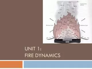
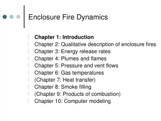
Ceiling Flames Carleton University, 82.583 (CVG****), Fire Dynamics II, Winter 2003, Lecture # 2
Ceiling Flames • Flame impinges on ceiling & spreads out radially, even if ceiling is non-combustible Heskestad & Hamada ( 93 to 760 kW) Flame extension, rf (m) rf = 0.95 (l - H) Eqn (2-29) Heskestad flame length (burning in open) l = 0.235 - 1.02 D Eqn (2-3) Carleton University, 82.583 (CVG****), Fire Dynamics II, Winter 2003, Lecture # 2
Ceiling Flames • Ceiling flames may ignite combustible or damage non-combustible ceiling elements, cables and pipes • Ceiling flames enhance thermal radiation to floor • augment burning rate of burning item • augment flame spread over burning item • augment heating or remote combustibles (targets) Carleton University, 82.583 (CVG****), Fire Dynamics II, Winter 2003, Lecture # 2
Ceiling Flame Increases Flame Spread & Burning • Consider burning of 0.76 m x 0.76 m slab of PMMA in an enclosure allowing air access from four sides • Max rate of burning ~ 3 x open-burning rate • Achieved in approximately 1/3 the time Carleton University, 82.583 (CVG****), Fire Dynamics II, Winter 2003, Lecture # 2