Download
1 / 57
570 likes | 704 Views
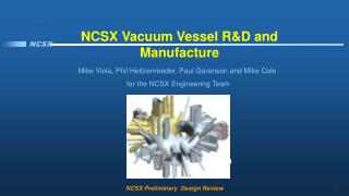
FIRE Vacuum Vessel and Remote Handling Overview. B. Nelson, T. Burgess, T. Brown, D. Driemeyer, H-M Fan, K. Freudenberg, G. Jones, C. Kessel, P. Ryan, M. Sawan, M. Ulrickson, D. Strickler, D. Williamson FIRE Physics Validation Review March 31, 2004. Presentation Outline . Vacuum Vessel

E N D
FIRE Vacuum Vessel and Remote Handling Overview B. Nelson, T. Burgess, T. Brown, D. Driemeyer, H-M Fan, K. Freudenberg, G. Jones, C. Kessel, P. Ryan, M. Sawan, M. Ulrickson, D. Strickler, D. Williamson FIRE Physics Validation Review March 31, 2004
Presentation Outline • Vacuum Vessel • Design requirements • Design concept and features • Analysis to date • Status and summary • Remote Handling • Maintenance Approach & Component Classification • In-Vessel Transporter • Component Replacement Time Estimates • Balance of RH Equipment • Design and analysis are consistent with pre-conceptual phase, but demonstrate basic feasibility of concepts FIRE Physics Validation Review: Vacuum Vessel and Remote Handling
FIRE vacuum vessel FIRE Physics Validation Review: Vacuum Vessel and Remote Handling
Vacuum vessel functions • Plasma vacuum environment • Primary tritium confinement boundary • Support for in-vessel components • Radiation shielding • Aid in plasma stabilization • conducting shell • internal control coils • Maximum access for heating/diagnostics FIRE Physics Validation Review: Vacuum Vessel and Remote Handling
Vacuum vessel parameters • Configuration: Double wall torus • Shielding water + steel with 60% packing factor • Volume of torus interior 53 m^3 • Surface Area of torus interior 112 m^2 • Facesheet thickness 15 mm • Rib thickness 15 - 30 mm • Weight of structure, incl ports 65 tonnes • Weight of torus shielding 100 tonnes • Coolant • Normal Operation Water, < 100C, < 1 Mpa • Bake-out Water ~150C, < 1 Mpa • Materials • Torus, ports and structure 316LN ss • Shielding 304L ss (tentative) FIRE Physics Validation Review: Vacuum Vessel and Remote Handling
Vessel port configuration FIRE Physics Validation Review: Vacuum Vessel and Remote Handling
Divertor piping Cryopump Divertor Midplane port w/plug Vessel ports and major components FIRE Physics Validation Review: Vacuum Vessel and Remote Handling
Nuclear shielding concept • Vessel shielding, port plugs and TF coils provide hands-on access to port flanges • Port plugs weigh ~7 tonnes each as shown, assuming 60% steel out to TF boundary FIRE Physics Validation Review: Vacuum Vessel and Remote Handling
Active and passive stabilizing sys. • passive plates ~25 mm thick copper with integral cooling Active control coils, segmented into octants IB and OB passive stabilizing conductor FIRE Physics Validation Review: Vacuum Vessel and Remote Handling
Passive conductor is also heat sink VV splice plate • Copper layer required to prevent large temperature gradients in VV due to nuclear heating, PFCs • Passive plates are required in most locations anyway • PFCs are conduction cooled to copper layer • Reduces gradient in stainless skin • Extends pulse length Cu filler (can be removed to allow space for mag. diag.) Cu Passive stabilizer VV PFC Tile Gasket FIRE Physics Validation Review: Vacuum Vessel and Remote Handling
FIRE and ITER first wall concepts similar • BE, Cu, SSt • Detachable FW panel • Cooling integral with FW panel (requires coolant connections to FW) ITER • BE, Cu, SSt • Detachable FW tiles • Cooling integral with Cu bonded to VV FIRE FIRE Physics Validation Review: Vacuum Vessel and Remote Handling
VV octant subassy w/passive structure Outboard passive conductor Inboard passive cond. Vessel octant prior to welding outer skin between ribs FIRE Physics Validation Review: Vacuum Vessel and Remote Handling
Vessel octant subassembly fab. (2) • Octant-to-octant splice joint requires double wall weld • All welding done from plasma side of vessel • Splice plates used on plasma side only to take up tolerance and provide clearance • Plasma side splice plate wide enough to accommodate welding the coil side joint FIRE Physics Validation Review: Vacuum Vessel and Remote Handling
Vessel analysis • Vessel subjected to numerous loading conditions • Normal operation (gravity, coolant pressure, thermal loads, etc.) • Disruption (including induced and conductive (halo) loads • Other loads (TF current ramp, seismic, etc.) • Preliminary FEA analysis performed • Linear, static stress analysis • Linear, transient and static thermal analyses • Main issues are disruption loads, thermal stresses FIRE Physics Validation Review: Vacuum Vessel and Remote Handling
Vacuum vessel mechanical loads FIRE Physics Validation Review: Vacuum Vessel and Remote Handling
Disruption effects on VV • Disruptions will cause high loads on the VV due to induced currents and conducting (halo) currents flowing in structures • Direct loads on vessel shell and ribs • Direct loads on passive plates • Reaction loads at supports for internal components • Divertor assemblies and piping • FW tiles • Port plugs / in-port components (e.g. RF antennas) • Dynamic effects should be considered, including: • Transient load application • Shock loads due to gaps in load paths (gaps must be avoided) • All loads should be considered in appropriate combinations e.g. Gravity + coolant pressure + VDE + nuclear / PFC heating + Seismic + … FIRE Physics Validation Review: Vacuum Vessel and Remote Handling
TSC runs confirm induced currents will concentrate in passive structures • Several TSC disruption simulations prepared by C. Kessel • VDE simulation used as basis for further analysis FIRE Physics Validation Review: Vacuum Vessel and Remote Handling
VDE analysis based on TSC runs • TSC output used to create drivers for Eddycuff model of VV • Peak loads applied to ANSYS model of VV • Halo loads from TSC mapped directly onto VV model Inner Face Sheet Outer Face Sheet Copper Plates EDDYCUFF EM Model ANSYS Structural Model FIRE Physics Validation Review: Vacuum Vessel and Remote Handling
I (A) 10-ms 300-ms 301-ms Reduced Filament Model (EDDYCUFF) TSC Filaments 301.6-ms 302.6-ms Plasma Evolution (TSC), from earlier data FIRE Physics Validation Review: Vacuum Vessel and Remote Handling
Typical Induced Eddy Currents Constant Current Vectors Proportional Current Vectors FIRE Physics Validation Review: Vacuum Vessel and Remote Handling
Current vs Time, Slow VDE (1 MA/ms) FIRE Physics Validation Review: Vacuum Vessel and Remote Handling
Typical EM loads due to Induced Current • Max force = -1 MN radial, +0.7 MN vertical per 1/16 sector (~11 MN tot) FIRE Physics Validation Review: Vacuum Vessel and Remote Handling
1 MA/ms VDE FZ F(lbs) FR Case 2 Case 1 t(s) Total Force vs time, induced + halo currents FIRE Physics Validation Review: Vacuum Vessel and Remote Handling
Typ. EM Force distr. due to Halo Current • Mapped directly from TSC to ANSYS, Halo current = 12-25% Ip • Max force = +0.13 MN radial, +1.2 MN vert. per 1/16 sector FIRE Physics Validation Review: Vacuum Vessel and Remote Handling
Y Z Pin 1 Reaction Fx=12662 Fz=10708 Lug 1 Reaction Fx=35121 Fy=40107 Fz=6987 X Pin 2 Reaction Fx=-22147 Fz=6614 Lug 2 Reaction Fx=-32540 Fy=-36384 Fz=-6473 Forces are in pounds Divertor loads from current loop • Loads based on PC-Opera analysis *ref Driemeyer, Ulrickson FIRE Physics Validation Review: Vacuum Vessel and Remote Handling
Combined stress, with VDE • Stresses due to gravity, coolant pressure, vacuum, VDE • VDE load includes direct EM loads on vessel (induced current and halo) and non-halo divertor loads Stress is in psi 1.5Sm = 28 ksi (195 Mpa) Stress is in psi VV Torus Ports FIRE Physics Validation Review: Vacuum Vessel and Remote Handling
Divertor attachment local stresses • Global model not adequate for analysis • Detailed model indicates adequate design Extended pins through the ribs and attached them to the outer shell Reinforced pins near connection points Increased hole Diameter to 0.7” Modified rib thickness to correct values 1.5Sm = 28ksi (195 Mpa) Stress is in psi FIRE Physics Validation Review: Vacuum Vessel and Remote Handling
Nuclear heating and thermal effects • Vacuum vessel is subject to two basic heat loads: • Direct nuclear heating from neutrons and gammas • Heating by conduction from first wall tiles (which in turn are heated by direct nuclear heating and surface heat flux) • A range of operating scenarios is possible, but the baseline cases for analysis assume: • 150 MW fusion power • 100 W/cm^2 surface heat load assumed on first wall, • 45 W/cm^2 is current baseline (H-mode) • > 45 W/cm^2 for AT modes • pulse length of 20 seconds (H-mode - 10T, 7.7 MA) • Pulse length of 40-ish seconds (AT mode - 6.5T, 5 MA) • Vessel is cooled by water • Flowing in copper first wall cladding • Flowing between walls of double wall structure FIRE Physics Validation Review: Vacuum Vessel and Remote Handling
Heat loads on vessel and FEA model • Fusion power of 150 MW • Surface heat flux is variable, 0, 50,100, and 150 W/cm2 analyzed C B D A Double wall Vac Vessel Cu cladding Tile, (36 mm) FIRE Physics Validation Review: Vacuum Vessel and Remote Handling
2-D temp distr (100W/cm2 surface flux) Inboard midplane Outboard midplane 20 s pulse 383 C 377 C 40 s pulse Be limit ~ 600C 619 C 622 C FIRE Physics Validation Review: Vacuum Vessel and Remote Handling
Peak Be temp vs heat flux, pulse length Be limit FIRE Physics Validation Review: Vacuum Vessel and Remote Handling
Nuclear heating distribution* Neutron wall loading Volumetric heating: plasma side, ss coil side, ss divertor * Ref M. Sawan FIRE Physics Validation Review: Vacuum Vessel and Remote Handling
Typical 3-D temp distribution in VV FIRE Physics Validation Review: Vacuum Vessel and Remote Handling
VV thermal deformation and stress Stress is in psi Peak High stress region localized Stress < 3xSm ( 56 ksi) Typical Deformation FIRE Physics Validation Review: Vacuum Vessel and Remote Handling
Combined stresses, 40 s pulse Stress is in psi • Nuclear heating, gravity, coolant pressure, vacuum Max Stress = 23 ksi, < 3Sm (56ksi) Max Deflection = 0.041 in. FIRE Physics Validation Review: Vacuum Vessel and Remote Handling
Combined stress, 10T, 7.7MA, 20 s pulse, with VDE is worst loading condition • Nuclear heating, gravity, coolant pressure, vacuum, slow VDE Stress is in psi Stress is in psi 3xSm Max Stress = 58 ksi, > 3Sm (56ksi), but very localized FIRE Physics Validation Review: Vacuum Vessel and Remote Handling
Combined stress, 6.5T, 5 MA, 40 s pulse, with VDE – not as severe as high field case • Nuclear heating, gravity, coolant pressure, vacuum, slow VDE Stress is in psi Max Stress = 46 ksi, < 3Sm (56ksi), also very localized FIRE Physics Validation Review: Vacuum Vessel and Remote Handling
Preliminary VV stress summary (1) Normal, High field (10T, 7.7 MA), 20 s pulse operation – O.K. FIRE Physics Validation Review: Vacuum Vessel and Remote Handling
Preliminary VV stress summary (2) High field (10T, 7.7 MA), 20 s pulse with VDE – a little high FIRE Physics Validation Review: Vacuum Vessel and Remote Handling
Preliminary VV stress summary (3) Normal, Low field (6.5T, 5 MA), 40 s pulse operation – O.K. FIRE Physics Validation Review: Vacuum Vessel and Remote Handling
Preliminary VV stress summary (4) Low field (6.5T, 5 MA), 40 s pulse with VDE – O.K. FIRE Physics Validation Review: Vacuum Vessel and Remote Handling
Conclusions of vessel analysis • Can vessel achieve normal operation? YES • Can vessel achieve pulse length? YES • 20 second pulse appears achievable • 40 second pulse should be achievable but depends on surface heat flux distribution and Be temperature • Can vessel take disruption loads? ITS CLOSE • Some local stresses over limit, but local reinforcement is possible • Additional load cases must be run FIRE Physics Validation Review: Vacuum Vessel and Remote Handling
What analysis tasks are next? • Optimized geometry and refined FEA models • Dynamic analysis with temporal distribution of VDE loads • Fatigue analysis, including plastic effects • Seismic analysis • Plastic analysis • Limit analysis FIRE Physics Validation Review: Vacuum Vessel and Remote Handling
Longer term issues for FIRE • Refine design • Develop design of generic port plug • Optimize divertor attachments for stress, remote handling • Design internal plumbing and shielding • Re-design / optimize gravity supports • Perform needed R&D • Select/verify method for bonding of copper cladding to vessel skin • Select/verify method for routing of cooling passages into and out of cladding • Develop fabrication technique for in-wall active control coils • Perform thermal and structural tests of prototype vessel wall, with cladding, tubes, tiles, etc. (need test facility) • Verify assembly welding of octants and tooling for remote disassembly/reassembly (need test facility) FIRE Physics Validation Review: Vacuum Vessel and Remote Handling
Remote Handling Overview FIRE Physics Validation Review: Vacuum Vessel and Remote Handling
Remote Handling* • Maintenance Approach & Component Classification • In-Vessel Transporter • Component Replacement Time Estimates • Balance of RH Equipment *ref T. Burgess FIRE Physics Validation Review: Vacuum Vessel and Remote Handling
Remote Maintenance Approach • Hands-on maintenance employed to the fullest extent possible. Activation levels outside vacuum vessel are low enough to permit hands-on maintenance. • In-vessel components removed as integral assemblies and transferred to the hot cell for repair or processing as waste. • In-vessel contamination contained by sealed transfer casks that dock to the VV ports. • Midplane ports provide access to divertor, FW and limiter modules. Port mounted systems (heating and diagnostics) are housed in a shielded assembly that is removed at the port interface. FIRE Physics Validation Review: Vacuum Vessel and Remote Handling
Remote Maintenance Approach (2) • Upper and lower auxiliary ports house diagnostic and cryopump assemblies that are also removable at the port interface. • Remote operations begin with disassembly of port assembly closure plate. • During extended in-vessel operations (e.g., divertor changeout), a shielded enclosure is installed at the open midplane port to allow human access to the ex-vessel region. • Remote maintenance drives in-vessel component design and interfaces. Components are given a classification and preliminary requirements are being accommodated in the layout of facilities and the site. FIRE Physics Validation Review: Vacuum Vessel and Remote Handling
Class 1 Class 2 Class 3 Class 4* Divertor Modules Limiter Modules Midplane Port Assemblies - RF heating - diagnostics First Wall Modules Upper and Lower Horiz. Auxiliary Port Assemblies - cryopumps - diagnostics Vacuum Vessel Sector with TF Coil Passive Plates In-Vessel Cooling Pipes - divertor pipes - limiter pipes Toroidal Field Coil Poloidal Field Coil Central Solenoid Magnet Structure Remote Handling,Classification of Components * Activation levels acceptable for hands-on maintenance FIRE Physics Validation Review: Vacuum Vessel and Remote Handling
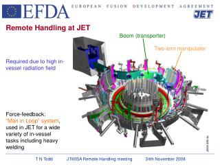
In-Vessel Remote Handling Transporter Cantilevered Articulated Boom (± 45° coverage) • Complete in-vessel coverage from 4 midplane ports. • Local repair from any midplane port. • Handles divertor, FW modules, limiter (with component specific end-effector). • Transfer cask docks and seals to VV port and hot cell interfaces to prevent spread of contamination. FIRE Physics Validation Review: Vacuum Vessel and Remote Handling