Download
1 / 24
250 likes | 640 Views
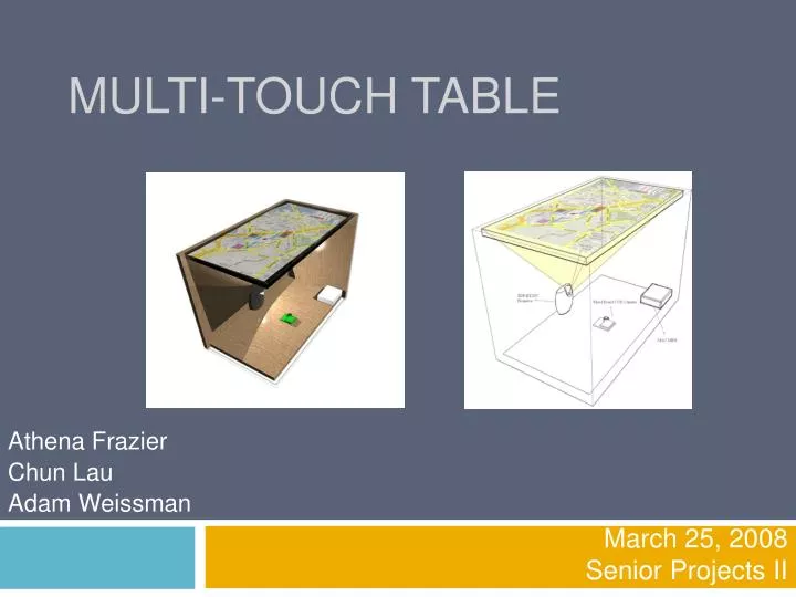
Multi-Touch Table. March 25, 2008 Senior Projects II. Athena Frazier Chun Lau Adam Weissman. Outline of Design Review. Project Overview User Interface Project Subsystems Input Output Cabinet Computer and Software Testing Foreseen Problems. Project Description.

E N D
Multi-Touch Table March 25, 2008 Senior Projects II Athena Frazier Chun Lau Adam Weissman
Outline of Design Review • Project Overview • User Interface • Project Subsystems • Input • Output • Cabinet • Computer and Software • Testing • Foreseen Problems
Project Description • The multi-touch table is a user interface device that will allow a user to interact with a computer through use of a multi-touch display. • The application to be demonstrated on the multi-touch display will be a game of pong.
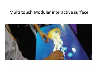
User Interface A user or users will be able to naturally interact with the application by apparently manipulating the workspace.
Project Subsystems • Input Subsystem • Output Subsystem • Cabinet Subsystem • Computer and Software
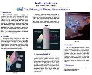
Input Subsystem • To be able to detect fingers placed on multi-touch screen, Infrared (IR) light will be injected into the side of a sheet of polished acrylic. • IR blobs will be formed at locations of frustration, which can be detected using a camera.
Frustrated Total Internal Reflection • This technique is referred to as Frustrated Total Internal Reflection (FTIR).
Input System: IR LED Arrays • To inject IR light into the acrylic sheet, IR LED arrays are placed on all four sides of the acrylic. • Aluminum U-Channel with holes drilled in it is used to hold multiple IR LEDs.
Input Subsystem: Compliant Surface • A compliant surface will be added to the acrylic sheet because of its abilities to: • Protect the acrylic from scratches • Block out light interference • Provide consistent blobs for detection • Improve the brightness of IR blobs • Show different touch pressures • Silicone Rubber was chosen as the compliant surface because it is transparent and shows all of the above traits.
Input Subsystem: The CameraFire-I Digital Camera Board • A requirement of the system is that the camera needs to be able to capture a screen size of 20” by 35” from less than 3’ away. Therefore, we will use the Fire-I Digital Camera Board. • The camera’s uncompressed VGA image capability prevents wasting unnecessary CPU usage. • One advantage of this camera is that it uses the Fire Wire interface. Fire Wire allows for a more consistent speed that is usually greater than speed of the USB interface.
Camera Considerations • Due to the requirements for a wide view capture, a specific lens is needed. All wide-angle lenses found were fish eye lenses. • This requires that a distortion correction filter be applied before the image can be used for blob detection. • An optical band or a high pass filter will be used to block out visible light. Sample of the Fish Eye Effect Image with corrected barrel distortion
Output Subsystem: The Projector Toshiba TDP-ET20U • A rear projection setup allows the projector to be placed inside the multimedia table. However, with the size of the multimedia table in mind, there is a strict requirement on the “throw” distance of the projector. • An extremely short throw distance projector was found to overcome the problem. • The Toshiba TDP-ET20U is able to display 40” diagonal screen image from a mere 1.7 feet away. • This projector also has a built-in function to invert output images for rear view projection applications, which prevents the need for adding a mirror inside the table.
Output Subsystem: Diffusion Layer • A diffusion layer is needed to provide a surface for the projected image to be displayed. • To diffuse the projected image through rear projection a sheet of Rosco Grey Projection Screen will be used. • Rosco Grey provides the added benefit of blocking ambient IR light.
Projector Cabinet Subsystem • To enclose and protect the system from ambient light, a cabinet will be built. • The cabinet is made of wood and will include fans in order to regulate the internal temperature. Acrylic Web camera Mac
Cabinet Subsystem cont. • Two fans and baffles will be installed on each side of the cabinet to increase ventilation. • Two doors will be installed to provide access to the cabinet if needed.
Computer Subsystem • The computer to be used will be a Mac Mini. • This computer was selected because of its small form factor and its ability to run multiple operating systems. The Mac Mini was also freely available. At the time of deciding on the computer, the operating system had not been chosen. • The Windows XP operating system was chosen because the Touchlib package is highly supported in Windows.
Programming for the Multi-Touch Table • Touchlib is an open source C++ software package that contains code to analyze data from a camera, detect IR blobs from within the data, interpret that IR blob data, and generate TUIO events for the application to interpret. • Since most operating systems only expect one mouse click at any single time, a new event and protocol must be used to interpret any number of touches, the TUIO protocol.
Touchlib: Hardware–Software Interface • Touchlib acts as a driver for the multi-touch table device so that the computer embedded inside can interpret touches from the user or users. • Individual applications can be written to interpret the data supplied from Touchlib and provide feedback to the display for the user or users.
Touchlib Calibration • The Touchlib library comes with software to calibrate and test the blob detection for a multi-touch setup. • Also, Touchlib comes with software to calibrate and test the camera that will be used with the multi-touch table.
Application Development • Many different platforms can be used to develop multi-touch applications utilizing TUIO events. Such platforms include: • Adobe Flash • Java • vvvv • C++ • At least one demo application will be developed with one of the platforms above.
Testing Strategies • All hardware subsystems will be tested thoroughly and independently. • Mechanical components (cabinet) • Silicone Rubber • Thermal testing • LED Arrays • Integration • Input System • Output System • Software • Touchlib • Hardware integration and blob detection • Applications • Single touch events • Using table hardware
Foreseen Problems • Hardware • Cabinet building • Thanks Todd (the Mechanical Engineer) for attempting to avoid some of these problems! • Ambient Light • Silicone Rubber • Fan placement • Overheating • Barrel Distortion • Fisheye effect • Software • Learning application platforms • Mac Mini not powerful enough