Download
1 / 44
460 likes | 788 Views
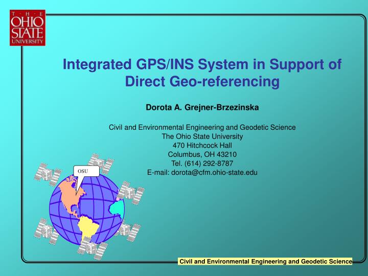
OSU. Integrated GPS/INS System in Support of Direct Geo-referencing Dorota A. Grejner-Brzezinska Civil and Environmental Engineering and Geodetic Science The Ohio State University 470 Hitchcock Hall Columbus, OH 43210 Tel. (614) 292-8787 E-mail: dorota@cfm.ohio-state.edu.

E N D
OSU • Integrated GPS/INS System in Support of Direct Geo-referencing • Dorota A. Grejner-Brzezinska • Civil and Environmental Engineering and Geodetic Science • The Ohio State University • 470 Hitchcock Hall • Columbus, OH 43210 • Tel. (614) 292-8787 • E-mail: dorota@cfm.ohio-state.edu
Presentation outline • Direct georeferencing concept • GPS/INS integration for positioning and orientation • INS component • GPS component • Primary integration architectures • Summary
Georeferencing: the Concept (1) • Sensor orientation, also called image georeferencing, is defined by a transformation between the image coordinates specified in the camera frame and the geodetic (mapping) reference frame. • requires knowledge of the camera interior and exterior orientation parameters (EOP) • interior orientation: principal point coordinates, focal length, and lens geometric distortion are provided by the camera calibration procedure • exterior orientation: spatial coordinates of the perspective center, and three rotation angles known as , , and
Georeferencing: the Concept (2) • Traditional aerial surveying • EOP determined from the aerotriangulation, defining correlation between ground control points and their corresponding image representations • requires scene pre-targeting • high cost • labor intensive
Georeferencing: the Concept (3) • Modern aerial surveying • EOP determined directly from integrated sensors such as GPS/INS or GPS antenna array • no scene pre-targeting (no ground control, except for GPS base station) • no aerotriangulation • low cost • allows automation of the data image processing
Automation of Aerial Survey • System augmentation by an inertial sensor offers a number of advantages over a stand-alone GPS • immunity to GPS outages • continuous attitude solution • reduced ambiguity search volume/time • high accuracy and stability over time contributed by GPS, enabling a continuous monitoring of inertial sensor errors • Result direct platform orientation (geo-referencing)
A Comparison of Mapping Scenarios Conventional Planning Ground Control Aerial Photography Film Processing Cost ¦ D a t e ¦ T i m e ¦ S c a l e e t c . Aerotriangulation Compilation Cartographic Reproduction Finishing Cost Direct Orientation Planning Aerial Photography Compilation Distribution and Editing Cost ¦ D a t e ¦ T i m e ¦ S c a l e e t c .
Direct Geo-referencing • Increased interest in the aerial survey and remote sensing community • need to accommodate the new spatial data sensors (LIDAR, SAR, multi/hyperspectral) • cost reduction of aerial mapping • decreased need for control points • maturity and cost-effectiveness of GPS/INS systems • GPS multi-antenna systems for less demanding applications • GPS/INS systems available: • experimental - University of Calgary, Center for Mapping OSU • commercial - Applanix
Direct Orientation Airborne System INS Position & Attitude (x, y, z) and (, , ) GPS Position & Time (x, y, z) Imaging Stereo Digital Images Digital Elevation Model Digital Orthophoto Hypsography Hydrography Topography
Digital camera GPS antenna INS Direct Orientation Land-based System
Direct Orientation Airborne System GPS Antenna INS PC Two Base Stations Camera GPS Receiver
Direct Georeferencing YBINS XBINS XC YC ZBINS ZM rM,INS rm,i,j • 3D INS coordinates in mapping frame • 3D object coordinates in model frame (derived from i,j stereo pair) attached to C-frame • 3D coordinates of point k in M-frame • boresight matrix between INS body frame and camera frame C • rotation matrix between INS body frame and mapping frame M, measured by INS • boresight offset components • scaling factor rM,INS rm,i,j rM,k YM rM,k XM s
GPS/INS Integration for Direct Orientation (direct geo-referencing) of the Imaging Component
Principles of Inertial Navigation • Principles defined in the i-frame (inertial) • Real time indication of position and velocity of a moving vehicle using sensors that react on the basis of Newton’s laws of motion • these sensors are called Inertial Measurement Units (IMU) • accelerometers • sense linear acceleration in inertial frame • does not sense the presence of a gravitational field • gyroscopes (sense rotational motion) • facilitate the rotation between navigation and INS body frames (in fact rotation with respect to the inertial frame is measured) • Integration with respect to time of the sensed acceleration to obtain velocity, and subsequent integration to obtain position
Inertial Navigation System (INS) • Provides self-contained independent means for 3-D positioning • Three gyros and three accelerometers (or less) • Accuracy degrades exponentially with time due to unbounded positioning errors caused by • uncompensated gyro errors • uncompensated accelerometer errors • fast degradation for low cost INS • High update rate (up to 256 Hz) • Mechanical (stabilized platform) systems • sense acceleration in inertial frame coordinatized in navigation frame • Strapdown systems (digital) • sense acceleration in inertial frame coordinatized in body frame
-Y Z -X INS LN-100 Body Axes
Primary Error Sources • The main sources of errors in an inertial navigation are due to the following factors: • The time rates of change of the velocity errors are driven chiefly by accelerometer errors and gravity anomalies • The attitude error rates are driven primarily by gyroscope errors • Three basic classes of errors • physical component error: deviation of inertial sensors from their design behavior (drifts, bias, scaling factors) • construction errors: errors in overall system construction such as mechanical alignment errors • initial conditions: errors that arise from imperfect determination of the initial position error, initial velocity error, and initial platform misalignment
8.8 GPS: 7.7 INS: Total Time 1867s 6.6 5.5 North Distance (Km) INS end position 4.4 GPS start & end position 3.3 2.2 1.1 0 0 0.4 0.8 1.2 1.6 2.0 (Latitude = 39.99° Longitude = -83.045 ) East Distance (km) Comparison of GPS and INS Free Navigation Trajectories (Road Test)
Strapdown INS • Strapdown system algorithms are the mathematical definitions of processes, which convert the measured outputs of IMUs that are fixed to the vehicle body axis, into quantities that can be used to control the vehicle (attitude, velocity and positions) • The outputs are angular rates and linear velocities along the orthogonal axes • The measured angular rates are converted into changes in attitude of the vehicle with respect to its initial orientation • The resulting attitude transformation matrix is used to convert the measured velocities from body axes to the reference coordinate system • The major algorithms are: • Start-up • Initialization • Generation of the transformation algorithm • Navigation
Strapdown INS • Start-up • the operational readiness is determined immediately after the power is turned on, by buit-in stimuli-response go/no go tests • this tests isolate system faults to a single gyro or accelerometer or control electronics • Initialization • as a dead reckoning device, it INS must know the initial conditions of the position and velocity from the external source • direction of the initial velocity vector is determined by the process of alignment • may include self-calibration
Initial Alignment • Process of initially locating the sensitive axes of the accelerometers with respect to the reference or navigation coordinate system axes (transformation matrix) • can be autonomous (without recourse to other equipment) • self-leveling: in the stationary mode it is accomplished by initial computation of the direction cosine transformation matrix to force the transformed velocity to have zero components in the horizontal reference directions • gyrocompassing: closed-loop process of locating true North by computing heading as an element of the transformation matrix that has been initially leveled (analogous to torquing the gimbals until the East gyro angular rate measurement is nulled) • can measure total drift rate about the vertical axes by recursive solution (self-calibration) • or slaved (by matching the starpdown system outputs to some external system
Strapdown INS Alignment • Coarse Alignment • For stationary system utilizes the gravity and earth rotation vectors as well as accelerometer and gyro outputs to determine the initial estimate of the transformation matrix (no sensor errors assumed)
where are the accumulated accelerometer outputs during the Coarse Self-Alignment Using Analytic Alignment Scheme Determination of pitch angle q and the roll anglef time interval D T Determination of azimuth angle y
Strapdown INS Alignment • Self-Corrective Alignment • because an initial estimate of the transformation matrix is available from the initial (coarse) alignment, the misalignment between the body and navigation frames can be modeled as a small angle rotation • the updating method consists of detecting error angles between these two frames via the processed accelerometer and gyro signals and generating a signal to the transformation computer in order to drive these angles as close to zero as possible • at the same time compensation is provided for the disturbance angular vibration
Calculated b D V Velocity t ib Body-Mounted f ( t ) d t ò Accelerometers 0 Gravity Known Computation Position Quaternion Computation for DCM Euler Angle Calculated Computation Attitude b b D q D q ib Earth Rate Body-Mounted in Calculated Computation Gyroscopes Heading Misalignment Correction Gyro drift Magnetic Misalignment Correction Heading Estimator Alignment (Optimal Estimator) n n D V D V ib nb Known Velocity n C _ b + + _ _ b D q nb _ + _ + _
Attitude Determination • Euler method • heading,pitch and roll, not suitable for strapdown system because the differential equations for their propagation contain trigonometric terms with singularities • nonlinear differential equations • Direction cosine method (DCM) • differential equations for DCM propagation are linear and very simple • the main disadvantage of DCM is that it has too many elements to be integrated • computational burden • Quaternion method
Attitude Determination • Quaternion method • quaternionQ is a quadruple of real numbers, Q = q0+q1i+q2j+q3k that evolve in accordance with a simple differential equation and are only one more in number than the minimum number required • three components define the axis of rotation, the fourth one – the amount of rotation • numerically stable characteristics • can be converted to direction cosines and Euler angles • preferred for strapdown systems • b, n are skew-symmetric matrices containing the rotation rates of the body-fixed frame w.r.t. inertial frame in body-fixed coordinates
Z Rotation Axis of Vector about which System a is Rotated in Order to Coordinate with System b
Error Sources in Numerical Solution (critical for updating transformation matrix) • Commutation errors • result from fixed-sequence numerical processing in the strapdown algorithm • can be minimized by increasing the update rate • Integration errors • due to discrete approximate solution of a continuous process • can be minimized by implementing sophisticated algorithms and increasing the update rate • Round-off errors • due to finite resolution of data • can be minimized by using double precision for critical operations • Quantization errors • analog-to-digital conversion of sensor measured outputs • can be minimized by increased storage hardware and mathematical modeling
Navigation Equations • A general navigation equation that describes the motion of a point mass over the surface of the earth f - acceleration due to applied force sensed by accelerometer g(r) - gravitational acceleration r – geocentric vector of vehicle position v(t) – velocity of the vehicle relative to the earth defined in the navigation system - earth rotation vector - angular rate of the navigation frame relative to the earth
Navigation Equations (cont) • the Earth’s rotation rate; L is the geodetic latitude, and lis the longitude. - the direction cosine matrix from body-fixed coordinates (b-frame) to navigation coordinates (n-frame) • the superscript “n” means a vector is coordinated in the n-frame
b D V ib Strapdown Inertial Mechanization Position Velocity n n D V D V ib nb n Body-Mounted Accelerometers C b + _ Gravity Computation Transformation Matrix Computation Attitude Euler Angle Computation b D q nb b b Earth and Vehicle Rate Computation D q D q ib Body-Mounted Gyroscopes in _ + b D V = Delta velocity from accelerometers ib b Dq = Delta q from gyros (angular rates) ib n C = Direction cosine matrix from b-frame to n-frame b
Why GPS/INS Integration? • GPS and INS have complementary operational characteristics • GPS contributes its white error spectrum, high accuracy and stability over time, enabling a continuous monitoring of inertial sensor errors • Calibrated INS offers high short-term accuracy and high sampling rate • INS is self-contained; no outages • GPS/INS offers a number of advantages over a stand-alone GPS • immunity to GPS outages and reduced ambiguity search volume/time for the closed-loop systems • and more importantly, continuous attitude solution • Implementation of a closed-loop error calibration allows continuous, on-the-fly (OTF) error update bounding INS errors, leading to increased estimation accuracy • Two primary integration modes • Loose coupling • Tight coupling (closed-loop)
GPS/INS Integration • Limitations • High cost of high quality INS • Mission objectives (what INS is needed and what can be afforded) • How complex is the integration scheme required to achieve the emission objectives
GPS/INS Integration • Loosely coupled mode • Separate filter to process GPS data • IMU measurements are processed by inertial navigation and attitude algorithms to give inertial position, velocity, and attitude solution • An integrated Kalman filter is then applied to combine the GPS and inertial solutions • The main disadvantage: positioning must be performed on the basis of IMU measurements alone when the number of tracked GPS satellites drops below four
GPS/INS Integration • Tightly coupled mode • A single Kalman filter is designed to process both sets of sensor data: raw GPS observations and IMU measurements • OTF IMU error calibration by a feedback loop • Allows use of GPS measurements from less than four satellites • High accuracy of the inertial system over short periods of time allows correction of undetected cycle slips affecting GPS measurements • Makes it possible to perform a faster and more robust OTF ambiguity resolution • Offers a possibility to support GPS tracking loop by a direct feedback from the integrated filter to maintain tracking during high dynamics • Offers superior performance compared to loosely coupled mode
User Interface Dialog/Menu INITIAL.DAT Get Data Processing Control Parameters Processing Organizer Initialization of the Kalman Filter IMU.DAT Filtering/Smoothing Uses differences between INS and GPS positions INS Positioning UDU Kalman Filtering/Smoothing INS Error Model Supporting Functions GPS.DAT GPS Positioning SMOOTHER.DAT Computation Diagram for Loosely Integrated GPS/INS System CONTROL.DAT
Strapdown Navigation Computation GPS/INS Kalman Filter Attitude Positions Error estimates Coordinate Transform Position & Velocity Computation Construct Model Parameters IMU Error Compensation IMU Quaternion Computation Euler Angle Computation State Estimate Propagation Measurement Residual Generation Covariance Propagation Double Differential GPS Computation Residual Testing Optimal Gain Computation Airborne Receiver Error Compensation OTF Ambiguity Resolution DD Observation Generation State Estimate Update Covariance Update Ground Receiver Architecture of Tightly Integrated GPS/INS System
Summary: Major Components of Integration Algorithm and Filter Design • Choice of coupling mode • Number of states that should be estimated • Whole-value filter states vs error states • How often should the filter be updated • How should the correlated measurements be treated • How to reduce the computational burden by proper exploitation of the sparseness of the dynamics matrix • How can the filter be used to detect the GPS or INS failure • How can filter be made robust against varying error characteristics of INS or GPS
Kalman Filter Model A: using Linear INS Error Model INS Psi-Angle Error Model • v, r, and are the velocity, position, and attitude error vectors respectively • is the accelerometer error vector • g is the error in the computed gravity vector • is the gyro drift vector. • subscript b stands for bias • subscript f stands for scaling factor Example: 24 INS States
Kalman Filter Model B:Using Nonlinear State Equation Nonlinear State Equation • v, r, and q are the velocity, position, and quaternion (associated with attitude determination) components • subscript b stands for bias • subscript f stands for scaling factor Example: 25 INS States