Download
1 / 22
220 likes | 368 Views
Application of robotics methods to Neutron and Synchrotron diffraction instrumentation. Department of Design, Development, Environment and Materials (DDEM) The Open University (UK). Jon James, Nov 2008. User group software: An example from Engineering diffraction

E N D
Application of robotics methods to Neutron and Synchrotron diffraction instrumentation Department of Design, Development, Environment and Materials (DDEM) The Open University (UK) Jon James, Nov 2008
User group software: An example from Engineering diffraction Strain Scanning Simulation Software
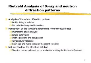
Measuring residual stress in Engineering samples/objects Context: Engineering diffraction • Aerospace, 2. Power generation, • 3.Materials research, 4. Cultural heritage…….
The Problem: SScanSS Beamtime Which measurement points ? Will it fit on the instrument? Choice of hardware? How long will it take? Instrument control Possible errors / collisions Sample repositioning Counting Neutrons
Planning Acquire sample model Setup measurement points and strain components Simulate experiment calculating; Instrument movements Count times Collisions Save measurement plan to HDF file Typical SScanSS usage - Planning
Execution Load measurement plan Place sample on instrument – measure exact location and input into software Run measurement plan simulation and output Instrument control file Collision warnings Count time estimations Archive complete experiment to plan to HDF file Typical SScanSS usage - Execution
Complex sample Sample model setup Articulated arm + Laser head
Measurement points are positioned within the sample Setting up Measurement points
Strain component(s) are defined at each measurement point Setting up Measurement vectors
Touch probe Sample + fiducial balls Initial sample position
Simulation of experiment to give: Instrument motor commands Neutron path lengths Experiment execution
Common frame-work for variety of systems Mathematically compact – minimises code Soluble forward and inverse problems Very difficult to do any other way Limitations…. Robotics
Robot types Serial robots Parallel robots
Sample is rotated about Q-vector is search of orientation that minimises path length Path length minimisation
Opportunities minimised by: Training on virtual instrument Careful planning of experiment Visual inspection of simulation prior to motor movements + last resort – Numerical Collision detection……… Collision Prevention
Collision Detection Collision detected! Bounding box tree -> computationally economicsolution
Responding to requests from existing collaborators New collaborations: KOWARI (ANSTO), VULCAN (SNS), JEEP (DIAMOND) Special projects Joint imaging / diffraction instruments (IMAT) Enable input of tomography models within SScanSS for locating hidden features Future plans
Using sample models derived from segmented Neutron tomography data will allow access to internal geometric and compositional features. Neutron Tomography models A cultural heritage illustration 1,2
Increases scientific output Enables New science Unifies user experience across facilities Good technical model Good collaboration model Good funding model Ticked boxes ? ? ? ?
Thank you for your attention and support Jon James
Dr. Salvatore Siano, Istituto di Fisica Applicata "N. Carrara"- IFAC, CNR-Italy and the Archaeological Museum of Florence, for their kind permission to use the material presented in panels (a), (b) and (c) of Figure 4. Dr Robert van Langh, for kind permission to use the image reproduced in panel (d) of Figure 4, (neutron image from NEUTRA, PSI, Switzerland). Research at ORNL sponsored by the Assistant Secretary for Energy Efficiency and Renewable Energy, Office of FreedomCAR and Vehicle Technologies, as part of the High Temperature Materials Laboratory User Program, Oak Ridge National Laboratory, managed by UT-Battelle, LLC, for the U.S. Department of Energy under contract number DE-AC05-00OR22725. The authors would like to also include an acknowledgement to William Barton Bailey for his efforts on the ORNL-NRSF2 facilities, drawings of the NRSF2 instrument and accessories and contributions to the implementation of SScanSS for NRSF2. The Open University for it’s continued support of this research. Acknowledgments