Download
1 / 24
240 likes | 244 Views
Subtalar fusion surgery is performed to relieve pain and correct severe foot deformity by achieving a solid bony union. According to the Association for the Study of Internal Fixation principles, compression across a fusion site promotes bone healing and also provides stability by maximizing bone-to-bone contact and limiting micro-motion. <br><br>The DynaNail Miniu00ae Fusion System from MedShape is an innovative nail system that maintains active compression across the subtalar joint using its proprietary internal NiTiNOL Compressive Element that automatically responds to changes in loading due to bone resorption or settling. <br><br>Read this file to learn about the Subtalar Fusion surgical technique guide using The DynaNail Miniu00ae Fusion System. For more information, visit www.medshape.com.

E N D
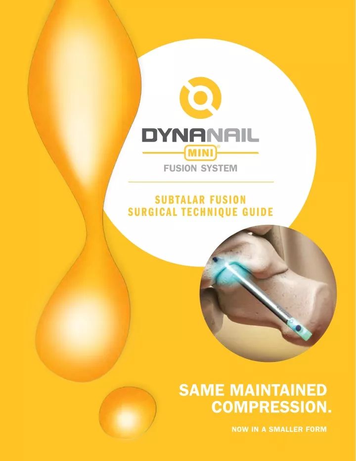
SUBTALAR FUSION SURGICAL TECHNIQUE GUIDE SAME MAINTAINED COMPRESSION. NOW IN A SMALLER FORM
TABLE OF CONTENTS 4 Introduction 5 Indications and Contraindications 6 Technical Specifcations 7 Accessory Instrumentation 8 Design Features 9 Instrument Tray 10 Quick Reference Guide 11 Surgical Technique 23 Ordering Information
INTRODUCTION Subtalar fusion surgery is performed to relieve pain and correct severe foot deformity by achieving solid bony union. According to the Association for the Study of Internal Fixation principles, compression across a fusion site is important for promoting bone healing. Compression also provides stability by maximizing bone-to-bone contact and limiting micro-motion. The clinical results for tibiotalocalcaneal (TTC) fusion support the biomechanical basis for applied compression at the joint site as both external and internal fxation devices have evolved over time to better meet this need.1 The DynaNail®MiniFusion System features MedShape’s patented and proven superelastic Internal NiTiNOL Compressive Element technology miniaturized for use in subtar fusion.2,3 Unlike traditional screws that lose compression within 1 mm of bone resorption, the DynaNail Mini is the only internal device for subtalar fusion that maintains active compression post-surgery in response to bone resorption or settling. Fixating the Nail Implant with two transverse screws allows for increased rotational stability in comparison to competitive screw devices. The Transverse Headless Screws in the talus and calcaneus provide superior fxation and decrease the risk of migration while helping to provide better overall joint stability. The DynaNail Mini Fusion System is offered in different diameters and lengths to accommodate varying patient anatomies with the amount of available NiTiNOL compression increasing with implant length. The Compressive Element is housed inside a rigid outer titanium body. The DynaNail Mini is provided with the NiTiNOL Element pre-stretched and pre-loaded on a disposable Nail Guide. The system also features a rigid, radiolucent carbon fber-flled polyether ether ketone (PEEK) Targeting Frame that is used to precisely position the Nail Implant across the joints and accurately drill and place the Screws. Housed in a single sterilization tray, the Frame and accompanying instrumentation provides the surgeon with a simple, reliable surgical approach. The streamlined surgical technique involves frst Nail Implant placement, insertion of the talar Headless Screw, then application of manual compression, insertion of the calcaneal Headless Screw, and fnally the release of the Nail Implant from the Targeting Frame. 1. Dupont KM, Shibuya N, Bariteau JT. Tibiotalocalcaneal Arthrodesis with Intramedullary Nails – Mechanobiological Background and Evolution of Compressive Technology. Global J Orthopedic Research, 2019. 1(5). 2. Yakacki CM, Gall K, Dirschl DR, Pacaccio DJ. Pseudoelastic intramedullary nailing for tibio-talo-calcaneal arthrodesis. Expert Rev Med Devices, 2011; 8(2): 159-66. 3. Ford SE, Kwon JY, Ellington K. Tibiotalocalcaneal Arthrodesis Utilizing a Titanium Intramedullary Nail With an Internal Pseudoelastic Nitinol Compression Element: A Retrospective Case Series of 33 Patients. J Foot Ankle Surg, 2019. 58(2):266-272. 4
INDICATIONS The DynaNail Mini Fusion System is indicated for: • Fracture fxation • Osteotomies • Reconstruction procedures • Non-unions • Fusions of large bones in the foot and ankle Contraindications • Patients with an active local or systemic infection. • Patients with an active soft tissue infection or osteomyelitis of foot and ankle. • Patients with severe peripheral vascular disease. • Patients with an obliterated medullary canal or other conditions that tend to retard healing such as blood supply limitations or previous infections. • Skeletally immature patients where the implant would cross open epiphyseal plates. • Patients with a dysvascular limb. • Patients with an insuffcient quantity or quality of bone to permit fusion of the joints or stabilization of the arthrodesis. • Patients with conditions that restrict his or her ability or willingness to follow postoperative instructions during the healing process. • Patients with foreign body sensitivity is suspected, or documented metal allergy or intolerance. Where material sensitivity is suspected, appropriate tests should be conducted and sensitivity ruled out prior to implantation. Internal NiTiNOL Compressive Element 5
TECHNICAL SPECIFICATIONS NAIL IMPLANT Available in 7 mm or 8 mm diameters and 60 – 100 mm lengths in 10 mm increments Sliding Calcaneal Screw Hole Proximal Talar Screw Hole Titanium Outer Body Sliding Element NiTiNOL Compressive Element 7 x 60 mm Amount of available NiTiNOL compression by implant length Nail Length Compression 60 mm 1.8 mm 2.8 mm 55 mm 70 mm 2.2 mm 7 x 70 mm 80 mm 2.8 mm 90 mm 3.4 mm 100 mm 4.0 mm 2.8 mm 65 mm 7 x 80 mm 2.2 mm 75 mm 7 x 90 mm 1.6 mm 85 mm 7 x 100 mm 1.0 mm 95 mm 6
SCREW END CAP • Length: 22 mm - 40 mm available in 2 mm increments • 3 mm Hex Head • Total Length: 7 mm • 1.3 mm Hex Head Sliding Calcaneal Screw Hole Proximal Talar Screw Hole Titanium Outer Body Major 6.15 mm Minor 4.05 mm Shaft 4.0 mm Minor 2.80 mm Major 4.0 mm Hex: 1.3 mm Sliding Element NiTiNOL Compressive Element ACCESSORY INSTRUMENTATION 7 x 60 mm Amount of available NiTiNOL compression by implant length The DynaNail Mini Targeting Frame is made of high-strength, rigid carbon fber PEEK to provide accurate drill targeting and placement of screws along with excellent visibility under fuoroscopy. Nail Length Compression 60 mm 1.8 mm 2.8 mm 55 mm 70 mm 2.2 mm Frame Operational Features 1. Retention Knob: Turn clockwise to secure the Nail Implant onto the Targeting Frame 2. Targeting Frame: Use to insert the Nail Implant and provide accurate placement of transverse Headless Screws 3. Manual Compression Wheel: Rotate clockwise to apply external compression 4. Bone Apposition Sleeve: Use lasermarks to determine amount of manual compression applied 5. Step Numbers: Indicates order of steps involving the Targeting Frame 7 x 70 mm 80 mm 2.8 mm 90 mm 3.4 mm 100 mm 4.0 mm 5 2.8 mm 65 mm 7 x 80 mm 4 3 2.2 mm 75 mm 7 x 90 mm 2 1 1.6 mm 85 mm 7 x 100 mm 1.0 mm 95 mm 7
DESIGN FEATURES The DynaNail Mini Fusion System maintains active compression across the subtalar joint using its proprietary internal NiTiNOL Compressive Element that automatically responds to changes in loading due to bone resorption or settling. The unloading of the Compressive Element can be visualized on fuoroscopy via translation of the screw holes in the Sliding Element through the slot in the Outer Body. This is best visualized on A-P radiographs. 5 8 1 7 6 10 12 Out of the Package The DynaNail Mini is provided with the NiTiNOL Compressive Element pre-stretched and pre-loaded on the disposable Nail Guide. 4 Nail Guide Internal NiTiNOL Element 14 15 Nail Outer Body 16 21 2 3 17 20 18 19 Immediate Post-Surgery Once the Targeting Frame is removed, the Compressive Element is now in its stretched, activated position with the calcaneal screws oriented in the distal end of the slot and the Sliding Element extending plantarly from the Nail Body. Screw Position when Stretched Weeks to Months Post-Surgery As the Compressive Element unloads (i.e. recovers its stretched length) in response to bone resorption or settling, the calcaneal Screws will progressively shift proximally. Unloading of the Compressive Element can be visualized on radiographs by the position of the screws and the length of the transparent region proximal to the Sliding Element. The Compressive Element has completely unloaded when the calcaneal Screw is at the proximal end of the slot and the transparent region is no longer visible. Screw Position after Unloading 8
INSTRUMENT TRAY 5 28 8 1 31 7 6 9 29 30 10 12 4 14 15 32 16 21 2 3 17 20 18 19 Instrument 1.3 mm T-Handle Driver 3 mm Hex Driver 2 mm Hex Driver Blue-Handle Ratchet Driver Targeting Frame Bone Apposition Sleeve Compression Knob Retention Knob 6.5 mm Guide Sleeve Part No. 2900-01-0130 2900-01-0300 2900-01-0200 2900-12-0000 2900-07-0000 2900-09-0078 2900-08-0000 2900-10-0000 2900-02-0650 2900-02-0400 2200-05-0070 2900-16-075 2900-16-080 2900-16-085 Qty 1 1 2 1 1 1 1 1 2 2 1 1 1 1 2 1 4 1 Instrument Guidewire, 2.4 x 380 mm Soft Tissue Protector Removal Tool, Strike Plate Assembly Removal Attachment Trial Sizer (60-100 mm) Trial Sizer (110-140 mm) Connection Screw Part No. 2900-04-0380 2900-13-0000 2200-24-0002 Qty 3 1 1 1. 2. 3. 4. 5. 6. 7. 8. 9. 10. 4.0 mm Drill Guide 11. 7.0 mm Cannulated Drill 12. 7.5 mm Cannulated Drill 13. 8.0 mm Cannulated Drill 14. 8.5 mm Cannulated Drill 15. 4.0 mm Transverse Screw Drill 2900-03-0400 16. Removal Tool Slap Hammer 17. 2 mm Steinmann Pin 18. Screw Depth Gauge 19. 20. 21. 22. 23. 24. 25. 26. End Cap Holder 27. Fenestration Drill, 2.5 mm x 6" 2201-09-0025 28. Guidewire Targeting Arm 29. Short Stylus 30. Long Stylus 31. Stylus Sleeve 32. Guidewire Targeting Screw 33. Stylus Paddle 34. Screw Locator 2900-18-0000 2900-15-0001 2900-15-0000 ED-10806 2900-19-0000 1 1 1 1 1 1 1 1 1 1 1 1 1 2900-05-0000 2900-05-0001 2900-05-0002 2900-05-0003 2900-05-0004 2900-05-0005 2900-05-0006 2200-24-0003 2200-19-0020 2900-17-0000 BOTTOM OF TRAY 11 13 22 23 25 24 26 27 Note: Additional removal tools available upon request. 9
QUICK REFERENCE GUIDE The following is a general overview of the DynaNail Mini Surgical Technique intended to be used as an easy reference. A more detailed surgical technique including technical tips and pearls is described in the following pages. The bold numbers in brackets correspond to the numbers marked on the Targeting Frame (A) and are intended to be used as a guide for the order of steps taken with the DynaNail Mini Targeting Frame. 1. Insert Guidewire, targeting the tip anterior to the fbula and toward the anterior third of the talar body. 2. Ream entry canal using a 0.5 mm size larger than selected nail diameter. 3. Determine Nail length using Trial Sizer. 4. Assemble Targeting Frame and attach Nail Implant. 5. Insert Nail Implant into reamed canal. 6. Drill and insert Transverse Talar Screw across the talus. [1] 7. Apply external compression by turning the Manual Compression Knob. [2] 8. Drill and insert Transverse Calcaneal Screw across the calcaneus. [3] 9. Release Nail Implant from the Targeting Frame. [4] 10. Insert End Cap and close incisions. A Step Guides 10
SURGICAL TECHNIQUE 11
1 Surgical Approach With the patient in a supine or lateral position, make a lateral incision. The extensor digitorum brevis can be split or elevated in a distal direction. Ensure that the crossing branch of the sural nerve to the dorsal intermediate branch of the superfcial peroneal nerve and peroneal tendons are protected during exposure. 2 Joint Preparation Instruments Used: 1. Fenestration Drill, 2.5mm x 6" [27] Using a lateral approach, reduce the joint to the correct position by frst exposing the subtalar joint. Distract the joint using a lamina spreader. Prepare the joint by completely removing cartilage from the posterior and middle facets using a sharp osteotome, a curette, and a rongeur until there is exposed bleeding subchondral bone. Leave the overall contours of the bones intact. Once all cartilage is removed, use a sharp osteotome to “fsh-scale” the posterior and middle facets. The 2.5 mm Fenestration Drill can be used to aid in creating bleeding bone and feathering the joint surface. Assure that the bleeding bone surfaces are in apposition before proceeding. Place any graft material if desired. 12
3 Place the Guidewire Instruments Used: 1. Guidewire, 2.4 mm x 380 mm [19] Make a 2 cm incision down to the bone at the posterior-plantar junction of the calcaneal tuberosity. Compress the joint before placing the Guidewire and keep joint in proper orientation and under compression throughout procedure. Steinmann pins may be used to fxate the subtalar joint if desired. Guidewire Placement Tips On the lateral view, aim the Guidewire anterior to the fbula and toward the anterior third of the talar body. Refer to the “Safe Zone” in the image to the left. Advance the Guidewire until the Tip is about 2-3 mm short of the anterior cortex. Ensure that the trajectory of the Guidewire does not cross the fbula on lateral fuoroscopy. On A-P fuoroscopy, Guidewire should appear centered or slightly biased toward the medial side. If necessary, the foot may be plantar fexed to create more space to drill for the talar screw. Safe zone between dashed lines 13
4 Reaming Entry Canal Instruments Used: 1. Soft Tissue Protector [20] 2. 7.5 mm Cannulated Drill (if using 7 mm Nail Implant) [11] 3. 8.5 mm Cannulated Drill (if using 8 mm Nail Implant) [14] Place the Soft Tissue Protector over the Guidewire against the posterior aspect of the calcaneus. Select the cannulated drill that is 0.5 mm larger than the selected Implant diameter and insert over the Guidewire into the Soft Tissue Protector. Drill over the path of the Guidewire until the proximal tip of the drill is a few millimeters distal to the anterior cortex of the talus. TECH TIP • If difficult to insert the Nail Implant, then drill 1 mm larger than the selected Implant diameter. 5 Determining Implant Length Instruments Used: 1. Trial Sizer, 60 mm - 100 mm [23] Several methods are available to determine appropriate nail length. Option 1: Lasermarks on the Cannulated Drill may be read off the back of the Soft Tissue Protector. Subtract 40 mm from the lasermark reading to determine the necessary Nail Implant length (A). TECH TIP • Select a Nail Implant length that is at least 5 mm shorter than the tunnel depth to allow the Nail Implant to be inserted sub-flush and to accommodate for Manual Compression. A Transverse Talar Screw Hole: Verify that the fibula is not obstructed Option 2 (Recommended): Remove the Cannulated Drill and insert the Trial Sizer into the reamed tunnel until the proximal screw hole is in the desired position in the talus, as viewed on lateral fuoroscopy. The proximal screw hole should be just anterior to the fbula. Use the etched lines on the distal end of the Implant Trial to determine the appropriate position of the distal end of the Implant in the calcaneus (B). Distal end of Nail Implant: Verify at least 5 mm sub-flush to allow for manual compression TECH TIP • If the Trial Sizer is inserted over the Guidewire, the screw holes will not be visible. In such cases, remove the Guidewire. If necessary, the Guidewire can be reinserted through the Trial Sizer after sizing is determined. B 14
6 Implant Attachment Instruments Used: 1. Targeting Frame [5] 2. Bone Apposition Sleeve [6] 3. Compression Knob [7] 4. Retention Knob [8] 5. DynaNail Mini Implant Attach the pre-stretched DynaNail Mini Implant Assembly onto the Targeting Frame and turn the Retention Knob clockwise to securely tighten. Thread the Bone Apposition Sleeve onto the Compression Knob by turning counter-clockwise until it stops (A). With the Bone Apposition Sleeve oriented up, advance the Manual Compression Knob over the DynaNail Mini Assembly and down past the ball bearing until it clicks into place. TECH TIP • Before inserting the Nail Implant, check the drill targeting by inserting the Guide Sleeve, Drill Guide, and 4 mm Drill into the appropriate hole in the Targeting Frame and advance the Drill until it passes through the proximal screw hole in the Nail Implant. A DynaNail Mini Assembly Bone Apposition Sleeve Compression Knob Targeting Frame Retention Knob 15
7 Implant Insertion Instruments Used: 1. Targeting Frame [5] Insert the Nail Implant into the drilled canal such that the Arm of the Targeting Frame is on the lateral side of the foot. If necessary, mallet on the Retention Knob to help advance the Implant. Do NOT mallet on any other part of the Targeting Frame beside the Retention Knob. Use fuoroscopy to determine that proper depth has been reached. TECH TIPS • Check Implant positioning on A-P and lateral fluoroscopy before proceeding to the next step. Recommendations for Implant Placement: On lateral fuoroscopy, ensure that the fbula is not obstructing the proximal talar screw hole. The distal end of the Nail Implant can be visualized as a translucent area in the Nail Guide on lateral fuoroscopy. Transverse Talar Screw Hole: Verify that the fibula is not obstructed Distal end of Nail Implant: Verify at least 5 mm sub-flush to allow for manual compression 16
8 Provisional Fixation of Targeting Frame Instruments Used: 1. Steinmann Pin, 2 mm x 9" (quantity 2) [17] Provisional fxation is recommended for stabilizing the frame and ensuring proper screw placement. To provisionally fxate the Targeting Frame, drill two Steinmann Pins through the small holes anterior and posterior to the intended hole for drilling the Transverse Talar Screw hole. 17
9 Drilling for Transverse Talar Screw Instruments Used: 1. 6.5 mm Guide Sleeve [9] 2. 4 mm Drill Guide [10] 3. 4 mm Transverse Screw Drill [15] Insert the 6.5 mm Guide Sleeve into the appropriate hole on the Targeting Frame corresponding to the selected Nail Implant length. If necessary, make an incision where the Guide Sleeve contacts the skin. Insert the 4 mm Drill Guide into the Guide Sleeve. Do NOT rest the Drill Guide on the bone as this may alter the drilling trajectory. TECH TIPS • Ensure the incision does not push on the drill guide before drilling Using the 4 mm Transverse Stepped Drill, drill to the medial cortex through the proximal screw hole in the Nail Implant. Use fuoroscopy to ensure full drill depth has been reached. Advance the Drill Guide against the bone prior to the next step. TECH TIPS • Do NOT advance the Drill tip beyond the medial cortex such that the Drill extends past the taper. The end of the Headless Screw is tapered and will lose purchase on far cortex if over drilled. 18
9 10 Drilling for Transverse Talar Screw Instruments Used: 1. 6.5 mm Guide Sleeve [9] 2. 4 mm Drill Guide [10] 3. 4 mm Transverse Screw Drill [15] Measuring Screw Length Instruments Used: 1. Screw Depth Gauge [18] There are two methods for determining screw length: Insert the 6.5 mm Guide Sleeve into the appropriate hole on the Targeting Frame corresponding to the selected Nail Implant length. If necessary, make an incision where the Guide Sleeve contacts the skin. Insert the 4 mm Drill Guide into the Guide Sleeve. Do NOT rest the Drill Guide on the bone as this may alter the drilling trajectory. Option 2 The Screw Depth Gauge may be inserted through the Drill Guide. With the Drill Guide against the bone, read the lasermarks on the Depth Gauge off the back of the Drill Guide. Option 1 With the Drill Guide abutted to the bone, read the lasermarks on the Drill off the back of the Drill Guide. TECH TIPS • Ensure the incision does not push on the drill guide before drilling Using the 4 mm Transverse Stepped Drill, drill to the medial cortex through the proximal screw hole in the Nail Implant. Use fuoroscopy to ensure full drill depth has been reached. Advance the Drill Guide against the bone prior to the next step. TECH TIPS • Do NOT advance the Drill tip beyond the medial cortex such that the Drill extends past the taper. The end of the Headless Screw is tapered and will lose purchase on far cortex if over drilled. 19
11 Transverse Talar Screw Insertion Instruments Used: 1. 3 mm Hex Driver [2] 2. Blue-Handle Ratchet Driver [4] 3. Headless Screw Attach the 3 mm Hex Driver to the Blue-Handle Ratchet Driver. Remove the 4 mm Drill and Drill Guide from the Guide Sleeve. Place the Transverse Headless Screw onto the 3 mm Hex Driver and insert into the Guide Sleeve. The Transverse Headless Screw does not provide any tactile feedback to indicate when it is fully inserted. When the lasermarking on the 3 mm Hex Driver approaches the back of the Guide Sleeve, use lateral fuoroscopy while advancing the fnal turns, ensuring the Screw tip does not extend beyond the medial cortex of the talus. Remove the Hex Driver and Guide Sleeve from the Targeting Frame. TECH TIP • Do NOT use power for Headless Screw insertion. • Check on A-P fluoroscopy to verify screw depth. 12 Apply Manual Compression Ensure the plantar incision is big enough for the Bone Apposition Sleeve to butt against the bone before applying manual compression. To apply manual compression, turn the Compression Knob in a clockwise direction as indicated by the arrows on the Knob. The approximate amount of manual compression applied can be determined by reading the lasermarkings on the Bone Apposition Sleeve of the Targeting Frame and taking the difference before and after applying manual compression. IMPORTANT NOTE: The Compression Knob will disengage from the Targeting Frame once the distal end of the Nail Implant has reached the posterior cortex of the calcaneus to prevent it from being positioned outside the bone. Laser markings 20
13 Calcaneal Screw Drilling & Insertion Instruments Used: 1. 6.5 mm Guide Sleeve [9] 2. 4 mm Drill Guide [10] 3. 4 mm Transverse Screw Drill [15] 4. 3 mm Hex Driver [2] 5. Blue-Handle Ratchet Driver [4] 6. Headless Screw Insert the 6.5 mm Guide Sleeve and 4 mm Drill Guide into the distal hole on the Targeting Frame. Make an incision parallel to the sural nerve down to the calcaneus. Follow the same technique outlined in Steps 8 – 10 to drill a pilot hole and determine proper screw length. Screw insertion Insert a 4 mm Headless Screw using the 3 mm Hex Driver ensuring the Screw has reached but does not extend past the medial cortex in the calcaneus. Remove the Guide Sleeve. 14 Release Nail Instruments Used: 1. 2 mm Hex Driver [3] 2. Blue-Handle Ratchet Driver [4] Connection Screw Attach the 2 mm Hex Driver to the Blue-Handle Ratchet Driver. To release the Nail Implant from the Targeting Frame, insert the 2 mm Hex Driver into the back of the Retention Knob. Unscrew the Connection Screw by turning counterclockwise (A). A Releasing from Frame This will release the Sliding Element from the Nail Guide and activate the NiTiNOL Compressive Element. 21
15 Insert End Cap Instruments Used: 1. 1.3 mm T-Handle Driver [1] 2. End Cap Holder [26] 3. End Cap Place the End Cap onto the end of the 1.3 mm T-Handle Driver (A). Slide the End Cap Holder over the Entire Assembly until the End Cap Holder butts against the End Cap. Turn the T-Handle clockwise until several threads of the End-Cap extend past the tip of the End-Cap Holder (B). Thread the End Cap into the distal end of the Sliding Element in the Nail Implant until fnger tight. Check fnal positioning of Nail Implant using fuoroscopy (C). Assembling End Cap Holder A Close incisions per surgeon preference. B Final insertion of End Cap C 22
ORDERING INFORMATION DYNANAIL MINI IMPLANTS DYNANAIL MINI SINGLE USE INSTRUMENTS Part No. Description Part No. Description 2600-00-7060 DynaNail Mini, 7 mm x 60 mm 2200-19-0200 Steinmann Pin, 2 mm x 9" 2600-00-7070 DynaNail Mini, 7 mm x 70 mm 2201-09-0025 Fenestration Drill, 2.5 mm x 6" 2600-00-7080 DynaNail Mini, 7 mm x 80 mm 2900-16-070 Cannulated Drill, 7.0 mm 2600-00-7090 DynaNail Mini, 7 mm x 90 mm 2900-16-075 Cannulated Drill, 7.5 mm 2600-00-7100 DynaNail Mini, 7 mm x 100 mm 2900-16-080 Cannulated Drill, 8.0 mm 2600-00-8060 DynaNail Mini, 8 mm x 60 mm 2900-16-085 Cannulated Drill, 8.5 mm 2600-00-8070 DynaNail Mini, 8 mm x 70 mm 2900-03-0400 Transverse Screw Drill, 4 mm 2600-00-8080 DynaNail Mini, 8 mm x 80 mm 2900-04-0380 Guidewire, 2.4 mm x 380 mm 2600-00-8090 DynaNail Mini, 8 mm x 90 mm 2600-00-8100 DynaNail Mini, 8 mm x 100 mm 2600-03-4322 Headless Screw, 4 mm x 22 mm 2600-03-4324 Headless Screw, 4 mm x 24 mm 2600-03-4326 Headless Screw, 4 mm x 26 mm 2600-03-4328 Headless Screw, 4 mm x 28 mm 2600-03-4330 Headless Screw, 4 mm x 30 mm 2600-03-4332 Headless Screw, 4 mm x 32 mm 2600-03-4334 Headless Screw, 4 mm x 34 mm 2600-03-4336 Headless Screw, 4 mm x 36 mm 2600-03-4338 Headless Screw, 4 mm x 38 mm 2600-03-4340 Headless Screw, 4 mm x 40 mm 2600-05-0000 End Cap 23
This brochure is presented to demonstrate the surgical techniques utilized by Jeffrey Covell, M.D. (Danville, KY) and Terrence Philbin, D.O. (Orthopedic Foot & Ankle Center in Dublin, Ohio). MedShape, as the manufacturer of this device, does not practice medicine and does not recommend this or any other surgical technique for use on a specifc patient. The surgeon who performs any procedures is responsible for determining and utilizing the appropriate techniques for such procedure for each individual patient. MedShape is not responsible for selection of the appropriate surgical technique to be utilized for an individual patient. Always refer to the package insert, product label and/or product instructions prior to using any MedShape product. For further product information or to arrange a product demonstration, please contact your local MedShape representative or call Customer Service at 877-343-7016. You can also visit www.medshape.com. MedShape, Inc. 1575 Northside Drive, NW Suite 440 Atlanta, GA 30318 T: 877-343-7016 F: 877-343-7017 CAUTION: Federal (USA) law restricts this device to sale by or on the order of a physician. ©MedShape, Inc., 2020. All rights reserved. Printed in the USA. Pat.: http://www.medshape.com/patents.html. MK-10186 Rev 00. Issued 03/2020. DynaNail Mini is a registered trademark of MedShape, Inc. DynaFrame is a trademark of MedShape, Inc. All other trademarks are trademarks of their respective owners and holders.