Download
1 / 4
40 likes | 43 Views
ASME B16.47 SERIES A FLANGES CLASS 900 DIMENSIONS AND TECHNICAL DRAWINGS<br><br><br>WIDELY USED IN THE INDUSTRIES<br>Pumps, Valves, and vessels in manufacturing and food processing.<br>Pipe connections in industrial waterworks.<br>Heat exchangers and heating systems of all sizes.<br>Mining support.<br>Nuclear power systems.<br>Plumbing and mechanical systems.<br>Assemblies in the oil, gas, and petrochemical industries.<br>Fire protection systems.<br><br><br>Get In Touch<br>MARCEL PIPING PROJECTS SUPPLY PVT LTD<br>32/34,Office No.2, Shashi Kripa Bldg, Paowala Street, R R Mohan Roy Road, Mumbaiu2013400004.<br>Maharashtra (India).<br>Website:https://mar

E N D
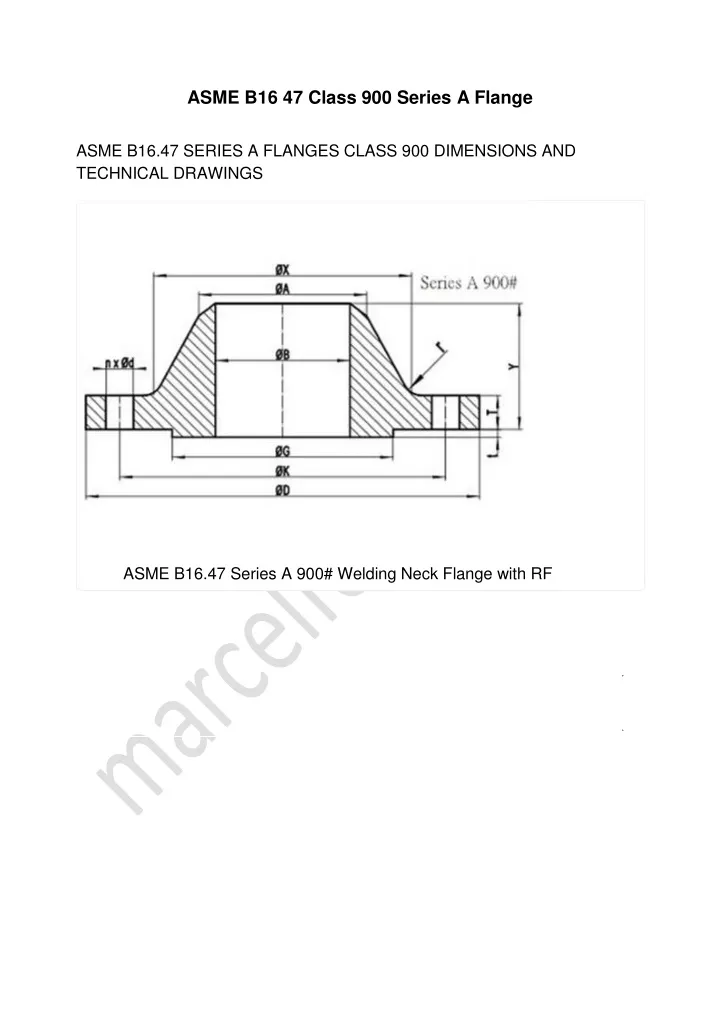
ASME B16 47 Class 900 Series A Flange ASME B16.47 SERIES A FLANGES CLASS 900 DIMENSIONS AND TECHNICAL DRAWINGS ASME B16.47 Series A 900# Welding Neck Flange with RF
(https:/ phone= (mailto: ASME B16.47 Series A Class 900 Blind Flange with RF 900# B16.47 SERIES A FLANGES DIMENSIONS B16.47 DIMENSIONS IN MM NPS D K G X 26″ 1085 952.5 749 775 28″ 1170 1022.4 800 832 30″ 1230 1085.8 857 889 32″ 1315 1155.7 914 946 34″ 1395 1225.6 965 1006 36″ 1460 1289.0 1022 1064 38″ 1460 1289.0 1099 1073 40″ 1510 1339.8 1162 1127 42″ 1560 1390.6 1213 1176 44″ 1650 1463.7 1270 1235 46″ 1735 1536.7 1334 1292 48″ 1785 1587.5 1384 1343 50″ – – – – 52″ – – – – 54″ – – – – 56″ – – – – Privacy - Terms 58″ – – – –
NPS D K G X 60″ – – – – General Note: All dimensions are in MM. D: outside diameter of fange. K: diameter of bolt circle. G: diameter of raised face. X: diameter of hub of fange. (https:/ phone= (mailto: NPS A TBL TWN Y 26″ 660.4 160.4 139.7 286 28″ 711.2 171.5 142.9 298 30″ 762.0 182.6 149.3 311 32″ 812.8 193.7 158.8 330 34″ 863.6 204.8 165.1 349 36″ 914.4 214.4 171.5 362 38″ 965.2 215.9 190.5 352 40″ 1016.0 223.9 196.9 364 42″ 1066.8 231.8 206.4 371 44″ 1117.6 242.9 214.4 391 46″ 1168.4 255.6 225.5 411 48″ 1219.2 263.6 233.4 419 50″ – – – – 52″ – – – – 54″ – – – – 56″ – – – – 58″ – – – – 60″ – – – – General Note: All dimensions are in MM. A: Diameter of hub top of WN. TBL: minimum thickness of blind fange. TWN: minimum thickness of WN fange. Y: length through hub of WN. t: 7mm height of RF for Class 900 Series A fange.
(https:/ phone= (mailto: NPS n d l r 26″ 20 2-7/8 2-3/4 11 28″ 20 3-1/8 3 13 30″ 20 3-1/8 3 13 32″ 20 3-3/8 3-1/4 13 34″ 20 3-5/8 3-1/2 14 36″ 20 3-5/8 3-1/2 14 38″ 20 3-5/8 3-1/2 19 40″ 24 3-5/8 3-1/2 21 42″ 24 3-5/8 3-1/2 21 44″ 24 3-7/8 3-3/4 22 46″ 24 4-1/8 4 22 48″ 24 4-1/8 4 24 50″ – – – – 52″ – – – – 54″ – – – – 56″ – – – – 58″ – – – – 60″ – – – – General Note: ASME B16.47 SERIES A CLASS 900 FLANGES INDUSTRIES AND APPLICATIONS WIDELY USED IN THE INDUSTRIES n: number of bolt holes. d: diameter of bolt hole. l: diameter of bolt. r: minimum fllet radius for WN. d and l are in inch units, while r is in mm unit. Pumps, Valves, and vessels in manufacturing and food processing. Pipe connections in industrial waterworks. Heat exchangers and heating systems of all sizes. Mining support. Nuclear power systems. Plumbing and mechanical systems. Assemblies in the oil, gas, and petrochemical industries. Fire protection systems.