Download
1 / 14
380 likes | 846 Views
Technical Drawings for Manufacturing. Types of Drawings. Orthographic Drawing 3 rd Angle Projection (North American Standard) 1 st Angle Projection (European Standard) Isometric & Oblique Drawings Shows object in 3-Dimensions Assembly Drawings

E N D
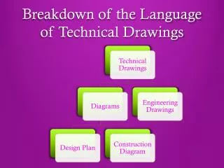
Types of Drawings • Orthographic Drawing • 3rd Angle Projection (North American Standard) • 1st Angle Projection (European Standard) • Isometric & Oblique Drawings • Shows object in 3-Dimensions • Assembly Drawings • Shows a group of parts that make up an assembly • Provides a Bill of Materials (B.O.M.)
Orthographic Drawings • 3rd Angle Projection is the most common type of Orthographic Drawings in North America • Orthographic drawings show parts in as many views as required to provide the information necessary for manufacturing the component • Typically include a Front, Top & Side view as well as Center Lines, Hidden Lines and Dimensions
Line Types • Visible Lines • The ones that outline your actual object • Hidden Lines • Show changes in geometry behind the durface you are looking at (think glass) • Center Lines • Identify the center point or symmetrical axes of a part • Section Lines • Show where a section view has been derived from and the direction of viewing • Hatch Lines • Show material type and that the material is sectioned (cut) in the location shown
Example Visible Line Hidden Line Section Line Center Mark Hatch Lines Center Line
Dimensions • Provide measurements on the drawing so the part can be manufactured • Dimensions should only be shown once on a drawing • Dimensions should be referenced from datums (critical features of your part) • Circles should be dimensioned where they are shown as rectangles when possible
Titleblock Information • Company Name • Designer Name • Date • Scale • Material • Sheet # of # • Etc……
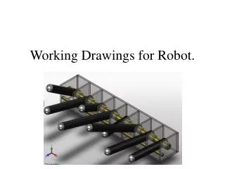
Assembly Drawings • Show a complete or sub-assembly in its assembled state or exploded state • Provides an identification system for individual components • Provides a Bill of Materials (BOM) to list descriptions and parts quantities that make up the assembly
Example Exploded View Collapsed View Bill of Materials