Download
1 / 5
50 likes | 54 Views
<br>Pumps, Valves, and vessels in manufacturing and food processing.<br>Pipe connections in industrial waterworks.<br>Heat exchangers and heating systems of all sizes.<br>Mining support.<br>Nuclear power systems.<br>Plumbing and mechanical systems.<br>Assemblies in the oil, gas, and petrochemical industries.<br>Fire protection systems.

E N D
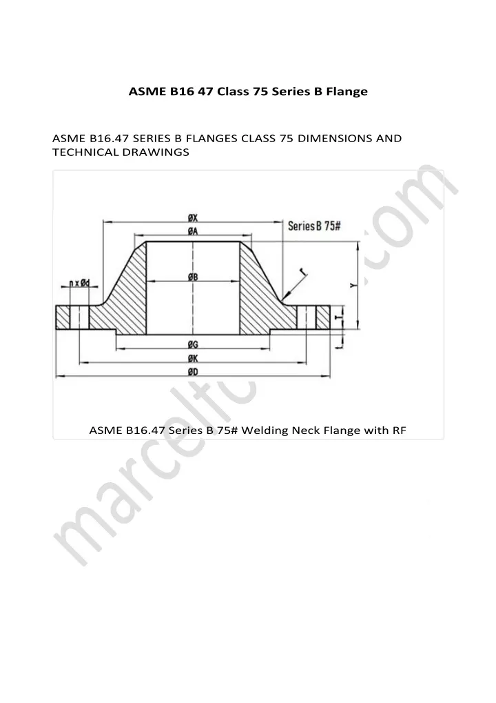
ASME B16 47 Class 75 Series B Flange ASME B16.47 SERIES B FLANGES CLASS 75 DIMENSIONS AND TECHNICAL DRAWINGS ASME B16.47 Series B 75# Welding Neck Flange with RF
ASME B16.47 Series B Class 75 Blind Flange 75# B16.47 SERIES B FLANGES DIMENSIONS B 1 6 . 4 7 D I M E N S I O N S I N M M NPS D K G X 26 760 723.9 705 676 28 815 774.7 756 727 30 865 825.5 806 778 32 915 876.3 857 829 34 965 927.1 908 879 36 1035 992.2 965 935 38 1085 1043.0 1016 986 40 1135 1093.8 1067 1037 42 1185 1144.6 1118 1087 44 1250 1203.3 1175 1140 46 1300 1254.1 1226 1191 48 1355 1304.9 1276 1241 50 1405 1355.7 1327 1294 52 1455 1409.7 1378 1345 54 1510 1460.5 1429 1397 y - Terms
56 1575 1520.8 1486 1451 1502 58 1625 1571.6 1537 D K G X 60 1675 1622.4 1588 1553 General Note: All dimensions are in MM. D: outside diameter of flange. K: diameter of bolt circle. G: diameter of raised face. X: diameter of hub of WN flange. NPS A TBL TWN Y 26 661.9 31.9 31.9 57 28 712.7 31.9 31.9 60 30 763.5 31.9 31.9 64 32 814.3 35.0 33.5 68 34 865.1 36.6 33.5 72 36 915.9 40.9 35.0 84 38 966.7 43.0 36.6 87 40 1017.5 43.0 36.6 91 42 1068.3 46.3 38.2 94 44 1119.1 47.7 41.4 103 46 1169.9 49.3 43.0 106 48 1220.7 52.5 44.6 110 50 1271.5 54.1 46.2 114 52 1322.3 55.7 46.2 119 54 1373.1 58.9 47.8 124 56 1423.9 60.4 49.3 133 58 1474.7 62.0 50.9 137 60 1525.5 65.2 54.1 143 General Note: All dimensions are in MM.
A: Diameter of hub top of WN. TBL: minimum thickness of blind flange. TWN: minimum thickness of WN flange. Y: length through hub of WN. t: 2mm height of RF for Class 75 Series B flange.
NPS n d l r 26 36 3/4 5/8 8 28 40 3/4 5/8 8 30 44 3/4 5/8 8 32 48 3/4 5/8 8 34 52 3/4 5/8 8 36 40 7/8 3/4 10 38 40 7/8 3/4 10 40 44 7/8 3/4 10 42 48 7/8 3/4 10 44 36 1 7/8 10 46 40 1 7/8 10 48 44 1 7/8 10 50 44 1 7/8 10 52 48 1 7/8 10 54 48 1 7/8 10 56 40 1-1/8 1 11 58 44 1-1/8 1 11 60 44 1-1/8 1 11 General Note: n: number of bolt holes. d: diameter of bolt hole. l: diameter of bolt. r: minimum fllet radius for WN. d and l are in inch units, while r is in mm unit. ASME B16.47 SERIES B CLASS 75 FLANGES INDUSTRIES AND APPLICATIONS Pumps, Valves, and vessels in manufacturing and food processing. Pipe connections in industrial waterworks. Heat exchangers and heating systems of all sizes. Mining support. Nuclear power systems. Plumbing and mechanical systems. Assemblies in the oil, gas, and petrochemical industries. Fire protection systems.