Download
1 / 14
280 likes | 1.07k Views
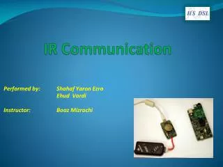
IR Communication Materials taken from a variety of sources including IR Remote for the Boe-Bot by Andy Lindsay The Plan: Use a TV Remote to Communicate with the Boe-Bot IR signal Sony TV remote control PWM The IR Signal

E N D
IR Communication Materials taken from a variety of sources including IR Remote for the Boe-Bot by Andy Lindsay
The Plan: Use a TV Remote to Communicate with the Boe-Bot IR signal Sony TV remote control PWM
The IR Signal • The IR detector is only looking for infrared that’s flashing on and off 38,500 times per second. • It has built-in optical filters that allow very little light except the 980 nm infrared. • It also has an electronic filter that only allows signals around 38.5 kHz to pass through. • This is the type of signal produced by the remote control. • This prevents IR interference from common sources such as sunlight and indoor lighting.
Important Concepts • Pulse width modulation (PWM): Pulse durations are used in many applications, a few of which are motor control, and communication. Since the IR detector sends low pulses that can be measured to determine what information the IR remote is sending, it's an example of using PWM for communication. • Carrier signal: The IR remote uses a 38.5 kHz "carrier signal" to transmit the pulse durations from the remote to the IR detector. • Communication protocol: A communication protocol is a set of rules for devices that have to exchange electronic messages. Protocols tend to have rules for voltages, the amount of time signals last, carrier signal frequencies and/or wavelengths, and much more. When two or more devices follow the rules of a given protocol, they should be able to communicate and exchange information.
The TV Remote Control • You must configure your universal remote so that it sends PWM messages to a television set using the SONY protocol. • TV remote setup • Press and release the TV key. • Press and hold the SET key until the indicator LED on the remote turns on and stays on. • Use the digit keys to enter 0001. The LED may turn off briefly as you press each digit. • VCR remote setup • Press and release the VCR key. • Press and hold the SET key until the indicator LED on the remote turns on and stays on. • Use the digit keys to enter 1028. The LED may turn off briefly as you press each digit.
Protocol Details • This message consists of thirteen negative pulses that the BASIC Stamp can easily measure. • 1: the start pulse, which lasts for 2.4 ms. • 2-13: will either last for 1.2 ms (binary-1) or 0.6 ms (binary-0). • 2-8: indicates which key is pressed. • 9-13: indicate if the message is being sent to a TV, VCR, CD, DVD player, etc. • Pulses are transmitted in least significant bit first fashion. • the first data pulse is bit-0. • the next data pulse is bit-1 • Etc. • If you press and hold a key on the remote, the same message will be sent over and over again with a 20 to 30 ms rest between messages.
How the IR Detector Works • The Boe-Bot IR receiver is the same detector found in many TVs and VCRs. • This detector sends a low signal whenever it detects IR flashing on/off at 38.5 kHz and a high signal the rest of the time. • When the IR detector sends low signals, the processor inside a TV or VCR measures how long each of the low signals lasts. Then, it uses these measurements to figure out which key was pressed on the remote. • Like the processor inside a TV, the Basic Stamp can be programmed to detect, measure, store, and interpret the sequence of low pulses it receives from the IR detector.
PULSIN Command • Complementary command to PULSOUT • The syntax for the PULSIN command is • PULSIN Pin, State, Variable • Pin: the I/O pin for measuring the pulse. • State is used to determine whether the pulse is a high pulse (1) or a low pulse (0). • Variable stores the pulse duration measured by the BASIC Stamp. • The IR pulses are negative pulses. To measure them with the IR detector circuit, you will have to use the command: • PULSIN pin#, 0, variableName • pin# is the pin connected to the IR detector; pin 9 in the previous slide.
Using PULSIN time VAR Word counter VAR Word DO PULSIN 9, 1, time IF (time > 1000) THEN counter = counter + 1
Interpreting the IR Message • The Idea: represent the pulse sequence as a bit sequence. • The IR message consists of thirteen pulses with the following format: • 1: the start pulse lasts for 2.4 ms. • 2-13: will either last for 1.2 ms (binary-1) or 0.6 ms (binary-0). • Map the duration of pulses 2-8 to their corresponding binary value • Use PULSIN and RCTIME to measure the pulse duration • Use the .BIT modifier to create the corresponding binary representation
How It Works remoteCode VAR Byte remoteCode = 0 RCTIME is used because the IF…THEN statement does not finish until after the next data pulse has already begun. Since the start of the pulse (its negative edge) is missed while the IF…THEN statement is executing, PULSIN cannot properly detect the beginning of the pulse.
Code Sample time VAR Word remoteCode VAR Byte remoteCode = 0 DO RCTIME 9, 1, time LOOP UNTIL time > 1000 PULSIN 9, 0, time IF time > 500 THEN remoteCode.BIT0 = 1 RCTIME 9, 0, time IF time > 300 THEN remoteCode.BIT1 = 1 RCTIME 9, 0, time IF time > 300 THEN remoteCode.BIT2 = 1 … RCTIME 9, 0, time IF time > 300 THEN remoteCode.BIT5 = 1 RCTIME 9, 0, time IF time > 300 THEN remoteCode.BIT6 = 1 DEBUG CRSRXY, 4, 3, BIN8 remoteCode, CRSRXY, 14, 3, DEC2 remoteCode