Download
1 / 19
190 likes | 619 Views
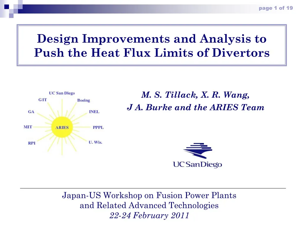
Design Improvements and Analysis to Push the Heat Flux Limits of Divertors. M. S. Tillack, X. R. Wang, J A. Burke and the ARIES Team. Japan-US Workshop on Fusion Power Plants and Related Advanced Technologies 22-24 February 2011. Summary of progress since February 2010.

E N D
Design Improvements and Analysis to Push the Heat Flux Limits of Divertors M. S. Tillack, X. R. Wang, J A. Burke and the ARIES Team Japan-US Workshop on Fusion Power Plants and Related Advanced Technologies 22-24 February 2011
Summary of progress since February 2010 • Last year we showed steady-state thermal-hydraulic and elastic structural analysis for four divertor concepts • Plate, T-tube, Finger, Plate + finger • Progress has been made for each concept: • Pin fins added to the plate design, experimental verification • Optimized T-tube slot and manifold • Modified finger configuration, optimized jet layout • Combination finger/plate concept design and fabrication • More sophisticated analysis techniques have been used: • Elastic-plastic analysis to push beyond 3Sm • Transient analysis (“birth to death”)
The plate divertor attempts moderately high performance with few parts and simple construction • ~768 unitstotal (16 sectors x 2 up/down x 2 slots x 2 plates x 6 units) • Inner (floating) steel cartridge • Slot jet cooling • Simple connection to a single external joint Coolant flow paths
In Thermal hydraulic experiments demonstrate very high heat transfer for slot jet cooling with pin fins Mass flow rate [g/s] Heated brass shell • Pin-fins with ~260% more surface area improve cooling performance by ~150%–200% while increasing pressure drop by ~40–70% • h > 50 kW/(m2K) is possible Pp*/P* Nup /Nu Nominal operating condition Re (/104)
The T-tube divertor was developed in ARIES-CS T. Ihli, A.R. Raffray, S. Abdel-Khalik, M. Shin, ARIES Team, Design and performance study of the helium-cooled T-tube divertor concept, Fusion Engineering and Design 82 (2007) 249–264.
The T-tube design was optimized by tailoring the inlet channels and slot width • Tapering reduces eddies • More uniform slot flow results • Further shape optimization is ongoing, accounting for spatially varying heat flux
The design window based on temperature limits allows up to 13 MW/m2 Non-Tapered T-Tube Tapered T-Tube Uncertainty in temperature limit By reducing the slot size from 0.5 to 0.45 mm, the heat flux limit increased from 11 to 13 MW/m2
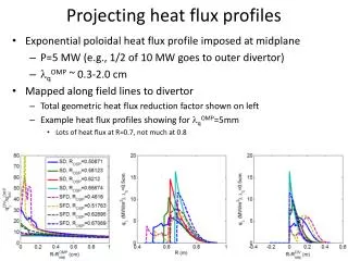
The design window based on 10% pumping power limit also allows up to 13 MW/m2 Note: these calculations all assume constant heat flux. Spatially varying profiles will allow higher local peak values.
The EU finger design was modified • No transition joint between W and FS • Transition is made at the end of the inlet manifold • We also added a 1-mm inner shell for double containment • Higher reliability is expected
Detail on the new finger configuration Fingers can be adapted into the manifold arrangement for the plate design concept Armor (W) Thimble(W-alloy) Ring (W-alloy)
Fingers can be combined with slot jets for localized HHF handling capability and minimum units • Cartridges with both slots and fingers can be combined • Limit fingers to zones with the highest heat flux q<10 MW/m2 q>10 MW/m2
The jet configuration was optimized • Temperature, pumping power and stress limits are the major reason for heat flux limits on plasma-facing components • Temperature is the most limiting constraint • Optimizing the layout of the jets (jet sizes, number of the cooling jets) can improve heat transfer with acceptable pressure drop • Iteration between thermal analysis and jet locations was performed to reduce the peak W temperature Example of modified jet-layout 600 ˚C 600 ˚C 700 ˚C 700 ˚C
The finger divertor can handle 15 MW/m2 without exceeding temperature or pumping power limits Velocity Wall heat transfer coefficient 600 ºC 700 ºC q”=15 MW/m2 q v=17.5 MW/m3 Tin/Tout=600/700 ºC P=10 MPa Vjet=332 m/s H.T.C=9.257x10⁴ W/m2K Pp/Pth =9.9% Max.T armor=2243 ºC Max. T thimble=1295 ºC Min. T thimble=864 ºC Temperature Temperature
Results of elastic stress analysis of the modified finger • Thermal loads: q”=15 MW/m2, qv=17.5 MW/m3 • Safety factor = Allowable stress(3Sm) / Maximum nodal stress (combined primary and secondary stresses) • The safety factor must be >1 (to meet the ASME 3Sm code) • The minimum safety factor is 0.3 in the armor and 0.9 in the thimble
Principal design criterion for inelastic analysis • In order to explore the limits of component performance, we do not restrict ourselves to elastic design criteria (i.e. 3Sm) • One simple inelastic failure criterion is based on accumulated strain: where is the maximum value of the principal strains accumulated over the operating life, and is 1/2 of the uniform elongation. • Other design criteria must be applied, as appropriate (e.g., ITER structural design criteria). Ideally, full nonlinear time-dependent analysis can provide full failure mode predictions.
Design criteria are satisfied by nonlinear stress analysis • Bilinear isotropic hardening material model is utilized • Allowable plastic strain (50% of uniform elongation) for pure W is 0.8% @270ºC and 1.0% @1200ºC. • Operating temperatures for heat flux up to 15 MW/m2: • VM-W (thimble + cylindrical ring): 800 <T<1300 ºC • Pure W (armor): 1000<T<2300 ºC • WL10 (front plate): 800<T<1300 ºC) • The maximum plastic strain is ~0.13% in the armor and 0.04% in the thimble.
Mechanical behavior of W in the divertor Elastic-plastic stress analysis suggests temperature limits of W likely will be more limiting than yield strength. The limited, non-overlapping temperature window is the problem. Crack growth may also dominate; fracture mechanics work is ongoing. Elastic analysis, 15 MW/m2 Elastic-plastic analysis, 15 MW/m2
Summary and future plans • Progress has been made on design and analysis of several advanced W/He divertor designs. • Our aim is to demonstrate a larger design window for plasma-facing components under “normal operating conditions” (15 MW/m2). • New efforts on elastic-plastic analysis are well underway. Efforts to model creep are also planned. • We will also quantify the limits under a select number of “off-normal” operating conditions.


![Heat Flux [Wm -2 ]](https://cdn3.slideserve.com/5899967/heat-flux-wm-2-dt.jpg)