Download
1 / 21
210 likes | 552 Views
Target Station and Target Damage Session -Introduction-. I. Bailey University of Liverpool / Cockcroft Institute RAL September 27 th 2006. Session Outline. 11:00 Introduction (20 min) - Ian Bailey 11:20 Target damage simulations (15 min) - Andriy Ushakov

E N D
Target Station and Target Damage Session-Introduction- I. Bailey University of Liverpool / Cockcroft Institute RAL September 27th 2006
Session Outline • 11:00 Introduction (20 min) - Ian Bailey • 11:20 Target damage simulations (15 min) - Andriy Ushakov • 11:35 Discussion (45 min) - All • 12:20 Alternative target design status (5 min) - Ian Bailey • 12:25 New results for crystallized W target from KEK (10 min) - Masao Kuriki • 12:35 Discussion (10 min)- All
Photons(≈ 10 MeV ) Helical Undulator (≈ 100 m) Electrons (150 GeV) Polarised Positrons (≈ 5 MeV) Conversion Target (0.4X0 Ti) Photon Collimator Undulator-Based Positron Source for ILC • The ILC requires of order 1014 positrons / s to meet its luminosity requirements. • A factor ~60 greater than the ‘conventional’ SLC positron source. • Undulator source should have lower stresses in the production target(s) and less activation of the target station(s) compared with a ‘conventional’ source. • Collimating the circularly-polarised SR from the undulator leads to production of longitudinally-polarised positrons.
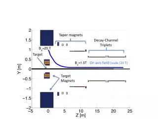
125 MeV e+ 400 MeV e+ ILC Positron Source Layout EUND - undulator TAPA - target station A TAPB - target station B Baseline layout of ILC with undulator at 150GeV position in main linac. Not to scale in any dimension!
Undulator Photon Beam (BCD) • Assume K=1, 1cm period, 100m long undulator. • Assume nominal ILC e- bunch structure. • Neglect collimation. • Target 450m downstream of undulator. • Total photon beam power: 145 kW • Average photon energy: 13MeV • Beam spot rms ≈1.5 mm (0.75mm in BCD) Simulations using SPECTRA 10MeV photons
Undulator Photon Beam (2) Target designed for 300kW average photon beam power. * “Proportional to undulator length”
Target Project Overview The University of Liverpool heads a EUROTeV-funded task to carry out design studies of the conversion target and photon collimator for the polarised positron source. Capture Optics Positron beam pipe/ NC rf cavity Target wheel Photon beam pipe Motor Vacuum feedthrough LLNL - draft design • Working in collaboration with SLAC and LLNL. • Developing water-cooled rotating wheel design. • 0.4 radiation length titanium alloy rim. • Radius approximately 1 m. • Rotates at approximately 1000 rpm.
Target Station Systems and Groups • LLNL • Target design • Computational studies • SLAC • Integration • Radiation studies • Liverpool / DL / RAL • Target design / prototyping • DESY • Target performance modelling • Cornell /BINP / KEK • Alternative target • ANL • Source modelling • Approx 400 m downstream of undulator • Key sub systems • Target wheel • Drive system • Cooling system • Vacuum system (10-8Torr) • Remote-handling system • Diagnostic and control systems • Target support systems • Photon collimator • Photon beam dump • Capture optics • NC rf cavity
LLNL - draft design Target Wheel Design Numbers refer to LLNL study of earlier solid-disc design. • Constraints: • Wheel rim speed determined by thermal load and cooling rate • Wheel diameter determined by radiation damage and • Materials fixed by thermal and mechanical properties and pair-production cross-section
LLNL - draft design LLNL - draft design Power Deposition & Cooling Approximately 10% of photon beam power is deposited in target wheel (≈30kW) Water fed into wheel via rotating water union on drive shaft.
Target Wheel Design • Recent drawings from DL design team • 5 spokes (following LLNL vibrational studies) • Thicker inner region to allow for stability, easier manufacture and balancing • Scaled to 1m diameter • LLNL may also extend driveshaft through vacuum chamber on both sides to allow separation of water union and drive system and prevent deflection of wheel in AMD field.
Radiation Effect Issues • Material Damage Need further analysis to gain confidence in numbers from earlier work. Currently investigating options for this work. Damage to nearby components (motors, seals, etc) needs to be checked. • Material Activation Analysis needs to be done on this for handling issues as well. Planning to have this done by whoever does the damage assessment. Needs to include looking at cooling fluid (water, liquid nitrogen). Possibly will need to include filtration on nitrogen loop to remove carbon decay products (soot). Provisional list from Tom Piggott, LLNL
Neutron Production See Target Hall Design and Activation session From TESLA study, expect 100mSv/h activation in target region. EU exposure limit for radiation workers is 20mSv/year… V. Bharadwaj - Positron Source Workshop, Daresbury 2005
Mechanical Design Issues • Thermal Modeling Complete modeling to check earlier results with varying beam parameters as well as varying wheel diameter and speed. • Structural Modeling Complete structural modeling for various cases analyzed thermally. Continue with vibration analysis, check internal modes, probably change to an odd number of spokes to avoid possible problems. • Repetitive Loading Check for effects of repetitive loading from beam, fatigue, creep, etc. Confer with metallurgist at LLNL. • Shaft Orientation/Deflection Evaluate moving to shaft supported on both ends. Possible vacuum seal issues, but simplifies motor and water union mounting. Evaluate movement of wheel under load conditions. Some of this already done with vibration modeling. • Wheel Size Evaluate thermal/structural/radiation damage limitations on wheel diameter. Also include looking at limitations imposed by other system components (capture optics, etc). • Target Station Handling Evaluate remote handling possibilities. Also look at packaging of target station to allow easy removal, and possible motion of target to move beam to extend target life. • Vacuum Design Requirements for vacuum in target station is determined by amount of differential pumping possible between the downstream accelerating cavity and the target station itself. Vacuum simulations /calculations required to determine achievable vacuums given outgassing from target + seal leakage. • Cooling System Design Layout and specification for target wheel cooling as well as AMD cooling system (and photon collimator?) • Piping/Electrical Layout • Instrumentation and controls Layout and specification of needed instrumentation and controls. • Wheel Balancing Look at possibilities for technique to balance rotating equipment, with care to consider effects of magnet loading. Provisional list from Tom Piggott, LLNL
Provisional list from Tom Piggott, LLNL AMD Related Issues • AMD Design Further evaluation of pulsed/continuous design. Look in more detail at cooling and stress issues. • Magnet Loading on Wheel Try to bring simulations and experimental data closer. Look at required motor power, additional heat input.
Provisional list from Tom Piggott, LLNL Integration Issues • Integrated Simulations Changes to undulator and collimator designs alter thermal load requirements of target. Effect of evolution in target / AMD design needs to be related to yield and polarization of finally captured positrons.
LLNL - preliminary LLNL - preliminary Eddy Current Simulations See AMD Session • Initial “Maxwell 3D” simulations by W. Stein and D. Mayhall at LLNL indicate: • ~2MW eddy current power loss for 1m radius solid Ti disc in 6T field of AMD. • <20kW power loss for current 1m radius Ti rim design. • However - Simulations do not yet agree with SLAC rotating disc experiment. • 8” diameter Cu disc rotating in field of permanent magnet. • Possibility of OPERA-3D simulations at RAL.
Provisional list from Tom Piggott, LLNL Other Issues • Other Target Technologies Stay aware of developments regarding alternative target materials, radiatively-cooled targets, liquid metal targets, etc. • Other Positron Source Technologies Stay aware of developments regarding conventional and Compton scattering sources.
UK Plans • Prototyping to demonstrate: • Stability of rotating target • Reliability of drive mechanism and vacuum seals. • Rotation of target in B field of capture optics. • Reliability of water-cooling system for required thermal load (average / peak?) • Engineering techniques for manufacture of water-cooling channels. • Liverpool, DL, and RAL plan to further develop the LLNL design and build prototypes of the target systems to determine the reliability. • Bid submitted to PPARC as part of LC-ABD. • Further EU funding? Coordination needed with other positron souce projects (CLIC) through ELAN, EUROTeV, etc.
UK Proposed Milestones • Goal 3. Construct and test a prototype to establish the mechanical stability of the target. • 3.1 Jul 07 - Infrastructure in place at Daresbury Laboratory. • 3.2 Aug 07 - Design of target test rig and instrumentation complete. • 3.3 Oct 07 - Construction of target test rig complete. • 3.4 Oct 07 -Construction of first prototype complete. • 3.5 Apr 08 -Testing of first prototype complete. • 3.6 Jun 08 - Data from first prototype analysed. • Goal 4. Construct and test a prototype to demonstrate operation of target in strong magnetic field. • 4.1 Nov 07 - Magnet design complete. • 4.2 Mar 08 - Magnet construction complete. • 4.3 Sep 08 - Construction of second prototype complete. • 4.4 Mar 09-Testing of second prototype complete. • 4.5 May 09-Data from second prototype analysed. • Goal 5. Construct and test a prototype to establish performance of the target cooling system. • 5.1 Feb 08 - Possible technologies for simulating thermal load identified. • 5.2 Jun 08 - Design of thermal load source and interface complete. • 5.3 Mar 09-Installation of thermal load in test rig complete. • 5.4 Jun 09 - Construction of third prototype complete. • 5.5 Jan 10 - Testing of third prototype complete. • 5.6 Feb 10 -Data from third prototype analysed.
Discussion • What’s missing from the R&D list? • Are all topics covered? • Is the proposed prototyping programme sufficient / necessary? • Do we have enough faith in radiation damage simulations to opt for smaller target wheel? • Scope for further collaboration / cooperation • Alternative targets discussed later in session