Download
1 / 7
70 likes | 78 Views
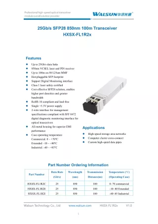
SFP-25G-CWDM-1370-10-T02, 1370nm CWDM 25.78Gbps SFP transceiver is designed for use in<br>25Gb/s data rate over single-mode fiber for link length 10Km

E N D
SFP-25G-CWDM-1370-10-T02#131010 25G 1370nm 10km SFP28 Transceiver Product 25G 1370nm 10km SFP28 Transceiver Model SFP-25G-CWDM-1370-10-T02 File No. SFP-25G-CWDM-1370-10-T02#131010 Version 1.0 Issuing Date 2020-6-4 Specification Revision Record Date Version Page Revision Description Prepare Approve 20210616 1.0 Zhang S All right reserved by Guilin GLsun Science and Tech Group Co., LTD. Without written permission, any unit or individual can’t reproduce, copy or use it for any commercial purpose. - 1 - Guilin GLsun Science and Tech Group Co., LTD. - 1 - Tel: +86-773-3116006 info@glsun.com Web: www.glsun.com
SFP-25G-CWDM-1370-10-T02#131010 Product Description SFP-25G-CWDM-1370-10-T02, 1370nm CWDM 25.78Gbps SFP+ transceiver is designed for use in 25Gb/s data rate over single-mode fiber for link length 10Km. The transceiver designs are optimized for high performance and cost effective to supply customers the best solutions for 25Gb/s single lane optical links. Product Feature Supports up to 25.78Gb/s bit rates Compliant to IEEE 802.3cc Compliant to SFF-8402 for SFP28 solution Digital Diagnostic Monitor Interface with SFF-8472 Hot pluggable SFP+ footprint 1370nm CWDM transmitter Applicable for 10Km SMF connection High transmission margin Low power consumption <1.5W Single 3.3V power supply Operating case temperature: 0 to 70 °C (commercial) Application 25.78 Gb/s single lane Other optical links Functional Diagram Guilin GLsun Science and Tech Group Co., LTD. - 2 - Tel: +86-773-3116006 info@glsun.com Web: www.glsun.com
SFP-25G-CWDM-1370-10-T02#131010 Absolute Maximum Ratings Parameter Symbol Min Max Unit Note Supply Voltage Vcc -0.5 4.0 V Storage Temperature TS -40 85 °C Relative Humidity RH 0 85 % Note: Stress in excess of the maximum absolute ratings can cause permanent damage to the transceiver. General Operating Characteristic Parameter Symbol Min Typ Max Unit Note Supply Voltage Vcc 3.13 3.3 3.47 V Supply Current Icc 450 mA Data Rate 25.78 Gb/s Operating Case Temperature Tc 0 70 °C Commercial Electrical Characteristics (TOP(C) = 0 to 70 ℃ ℃,VCC = 3.13 to 3.47 V) Parameter Symbol Min. Typ Max. Unit Note Transmitter Differential data input swing VINPP 120 800 mVpp 1 Tx Disable input H TDH 2.0 Vcc+0.3 V L TDL 0 0.8 Tx Fault output H TFH 2.0 Vcc+0.3 V 2 L TFL 0 0.8 Input differential impedance Rin 100 Ω Receiver Differential data output swing Vout,pp 340 650 800 mVpp 3 Rx Los Output H VOH 2.0 Vcc+0.3 V 2 L VOL 0 0.8 Guilin GLsun Science and Tech Group Co., LTD. - 3 - Tel: +86-773-3116006 info@glsun.com Web: www.glsun.com
SFP-25G-CWDM-1370-10-T02#131010 Note: 1. TD+/- are internally AC coupled with 100Ω differential termination inside the module. 2. Tx Fault and Rx LOS are open collector outputs, which should be pulled up with 4.7k to 10kΩ resistors on the host board. Pull up voltage between 2.0V and Vcc+0.3V. 3. RD+/- outputs are internally AC coupled, and should be terminated with 100Ω (differential) at the user SERDES. Optical Characteristics (TOP(C) = 0 to 70 ℃ ℃, TOP(I) =-40 to 85 ℃ ℃,VCC = 3.13 to 3.47 V) Parameter Symbol Min. Typ Max. Unit Note Transmitter Operating Wavelength λ -6.5nm 1271,1291, 1311,1331, 1351,1371 +6.5nm nm Ave. output power (Enabled) PAVE -3 +5 dBm 1 Side-Mode Suppression Ratio SMSR 30 dB Extinction Ratio ER 3.5 dB RMS spectral width(-20dB) Δλ 1 nm Dispersion penalty TDP 2.7 dB Relative Intensity Noise RIN -130 dB/Hz Receiver Operating Wavelength 1260 1610 nm Receiver Sensitivity(OMA) PSen -11 dBm 2 Receiver Sensitivity(OMA) PSen -13.8 dBm 3 Average Receiver Power Pimax -13.3 2 dBm LOSAssert Pa -30 dBm LOS De-assert Pd -12 dBm LOS Hysteresis Pd-Pa 1 5 dB Notes: 1. Average power figures are informative only, per IEEE 802.3cc. 2. Measured at the BER less than 1E-12, back to back. The measure pattern is PRBS 231-1with worst ER=4.5@ 25.78Gb/s. 3. Measured at the BER less than 5E-5, back to back. The measure pattern is PRBS 231-1with worst ER=4.5@ 25.78Gb/s. Guilin GLsun Science and Tech Group Co., LTD. - 4 - Tel: +86-773-3116006 info@glsun.com Web: www.glsun.com
SFP-25G-CWDM-1370-10-T02#131010 Pin Definition And Functions Pin Symbol Name/Description 1 VEET [1] Transmitter Ground 2 Tx_FAULT [2] Transmitter Fault 3 Tx_DIS [3] Transmitter Disable. Laser output disabled on high or open 4 SDA [2] 2-wire Serial Interface Data Line 5 SCL [2] 2-wire Serial Interface Clock Line 6 MOD_ABS [4] Module Absent. Grounded within the module 7 RS0 [5] Rate Select 0 8 RX_LOS [2] Loss of Signal indication. Logic 0 indicates normal operation 9 RS1 [5] Rate Select 1 10 VEER [1] Receiver Ground 11 VEER [1] Receiver Ground 12 RD- Receiver Inverted DATA out. AC Coupled 13 RD+ Receiver DATA out. AC Coupled 14 VEER [1] Receiver Ground 15 VCCR Receiver Power Supply 16 VCCT Transmitter Power Supply 17 VEET [1] Transmitter Ground 18 TD+ Transmitter DATA in. AC Coupled 19 TD- Transmitter Inverted DATA in. AC Coupled 20 VEET [1] Transmitter Ground Guilin GLsun Science and Tech Group Co., LTD. - 5 - Tel: +86-773-3116006 info@glsun.com Web: www.glsun.com
SFP-25G-CWDM-1370-10-T02#131010 Notes: 1. Module circuit ground is isolated from module chassis ground within the module. 2. should be pulled up with 4.7k – 10k ohms on host board to a voltage between 3.15V and 3.6V. 3. Tx_Disable is an input contact with a 4.7 kΩ to 10 kΩ pullup to VccT inside the module. 4. Mod_ABS is connected to VeeT or VeeR in the SFP+ module. The host may pull this contact up to Vcc_Host with a resistor in the range 4.7 kΩ to10 kΩ.Mod_ABS is asserted “High” when the SFP+ module is physically absent from a host slot. 5. RS0 and RS1 are module inputs and are pulled low to VeeT with > 30 kΩ resistors in the module. Typical Interface Circuit Recommended Power Supply Filter Note: Inductors with DC resistance of less than 1Ω should be used in order to maintain the required voltage at the SFP input pin with 3.3V supply voltage. When the recommended supply filtering network is used, hot plugging of the SFP transceiver module will result in an inrush current of no more than 30 mA greater than the steady state value Guilin GLsun Science and Tech Group Co., LTD. - 6 - Tel: +86-773-3116006 info@glsun.com Web: www.glsun.com
SFP-25G-CWDM-1370-10-T02#131010 Package Dimensions Ordering Information Part Number Description SFP-25G-CWDM-1370-10-T02 SFP28, up to 25.78Gb/s, CWDM, 1370nm, 10km, 0~70℃ Guilin GLsun Science and Tech Group Co., LTD. - 7 - Tel: +86-773-3116006 info@glsun.com Web: www.glsun.com