Download
1 / 35
370 likes | 847 Views
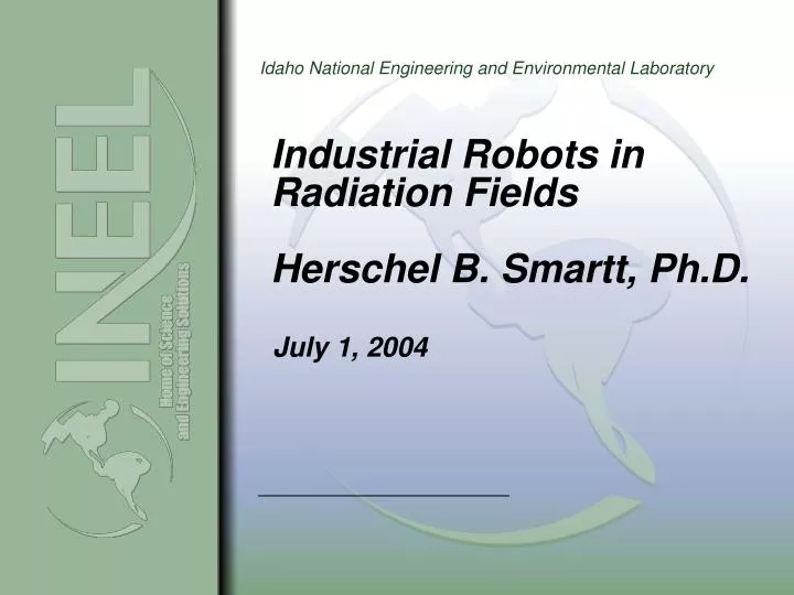
Industrial Robots in Radiation Fields Herschel B. Smartt, Ph.D. July 1, 2004 Industrial Robots in Radiation Fields What problem do we want to solve? Examples industrial robots Robot coordinate systems How do robots work? Degrees-of-freedom; axes-of-motion

E N D
Industrial Robots in Radiation FieldsHerschel B. Smartt, Ph.D. July 1, 2004
Industrial Robots in Radiation Fields • What problem do we want to solve? • Examples industrial robots • Robot coordinate systems • How do robots work? • Degrees-of-freedom; axes-of-motion • Motors, encoders, resolvers, limit and home switches • Radiation • Radiation hardening • Quick disconnects • End effectors • Robotics research Slide 1
Industrial Robots in Radiation Fields • We want to use industrial robots to weld lids on certain radioactive waste materials storage canisters. • We need to use robots because the radioactive exposure is too great in this specific application for personnel to be present. Robot 1 Robot 1 Storage canister Slide 2
Tool end Articulated Arm Robot 6-axis motion Floor mounted Slide 3
Cartesian robots Linear slides Slide 4
SCARA robots "Selective Compliant Assembly Robot Arm". Slide 5
3 Translation axes Y P2 X P1 Z Slide 6
Y P2 X P1 Z Slide 7
3 Translation axes 3 Rotation axes Y θ2 P2 X θ1 P1 Z θ3 Slide 8
3 or 4 axis 6 axis 3 to 5 axis Slide 9
Axis 6 6 degrees-of-freedom Axis 4 Axis 3 Axis 5 Axis 2 Axis 1 Slide 10
θ6 P Forward kinematics: for a specific robot geometry, given θ1, θ2, θ3, θ4, θ5, θ6 find P Inverse kinematics: for a specific robot geometry, given P find θ1, θ2, θ3, θ4, θ5, θ6 θ4 θ3 θ5 θ2 See, for example: P. J. McKerrow, Introduction to Robotics, Addison-Wesley, ISBN 0-201-18240-8, 1991. W. Khalil & E. Dombre, Modeling, Identification & Control of Robots, Taylor & Francis, ISBN 1-56032-983-1, 2002. θ1 Slide 11
Worker Category Legal Limit 18-year old male 5 rem/year Pregnant woman 500 millirem (mrem) during pregnancy Radiation environments Robot exposure 10 to 1000 rem/hr gamma radiation http://www.epa.gov/radiation/rert/radfacts.htm Slide 12
Motor 5 Motor 4 Motor 3 Motor 2 Motor 1 Slide 13
Servo motors and drives Radiation hardened motors are available. Slide 14
Optical encoders Slide 15
Encoder disks Plastic disk and sensing electronics are not radiation hardened. Absolute encoder disk Incremental encoder disk Slide 16
Timing Diagram: • CPR (N): The number of Cycles Per Revolution.One Shaft Rotation: 360 mechanical degrees, N cycles.One Electrical Degree (°e): 1/360th of one cycle.One Cycle (C): 360 electrical degrees (°e). Each cycle can be decoded into 1 or 4 codes, referred to as X1 or X4 resolution multiplication.Symmetry: A measure of the relationship between (X) and (Y) in electrical degrees, nominally 180°e.Quadrature (Z): The phase lag or lead between channels A and B in electrical degrees, nominally 90°e.Index (CH I.): The index output goes high once per revolution, coincident with the low states of channels A and B, nominally 1/4 of one cycle (90°e).Position Error: The difference between the actual shaft position and the position indicated by the encoder cycle count.Cycle Error: An indication of cycle uniformity. The difference between an observed shaft angle which gives rise to one electrical cycle, and the nominal angular increment of 1/N of a revolution. Encoder signals Slide 17
Resolvers Radiation hardened resolvers are available. Slide 18
Internal drive by precision gear boxes and timing belts sprockets Toothed belt Radiation hardened timing belts are available. Slide 19
Welding End Effector Tool Quick Disconnect Mounting Plate Seam Tracker/Profile Measurement Automatic Voltage Control Axis Wire Feed Positioner Oscillation Axis Video Camera Video Camera Wire Guide TIG Torch Slide 21
Video Camera • Clear view of cold wire TIG process operating at 350A • View area of ¾–1in. square at tip of tungsten • Arc on and off viewing modes with commanded switching • Camera position 4-7in. range from tip of tungsten • Viewing angles 40-55deg from torch axis • Minimum depth of focus of 1” • NTSC (color) or RS-170 (B&W) video output • Same camera system for leading and trailing cameras • Standard environmental requirements Slide 22
Video Camera Camera Views Leading Camera View Trailing Camera View Slide 23
Video Camera • Remote head camera system with out of cell CCU • 2/3” Radiation tolerant CID imager • 750 x 512 Imager pixels • Resolution: 450 TVL Horizontal, 400 TVL Vertical • RS-170, 30FPS, 2:1 Interlaced Video Output • 1x10⁶ rad total exposure (at 7x10⁵ rad/hr) • 7x10⁵ rad/hr maximum field strengths • Less rad damage when device is not energized • Camera Weight = 9.7 oz Slide 24
Robot welding cell: 8-axis motion Top linear slide robot Linear slide Slide 27
robot Weld torch Linear slide Slide 28
Drops of molten steel moving down the arc plasma. electrode molten steel drop molten steel drop weld pool
Weld torch Spot weld Slide 29
s s s s s s s s M M M M M M M M wire feeder operator power supply GUI volume to wfs & time X-axis motor arc length to voltage Y-axis motor Z-axis motor Weld quality Slide 30 bus
I/O Agent Block Diagram dead man tasks, state analog rules of behavior com port dead man I state digital Ethernet/TCP-IP high level messages serial port mid-level motion control Slide 31
s s s s s s s s M M M M M M M M wire feeder operator power supply GUI volume to wfs & time X-axis motor arc length to voltage Y-axis motor Z-axis motor Weld quality Slide 32
Industrial Robots in Radiation Fields • Discussed some aspects of using robots in radiation fields • Looked at some various types of industrial robots • Considered robot coordinate systems • Examined some aspects of the internal technology of robots • Considered problem of radiation hardening robots • Discussed some research on agent-based robot control Slide 33