Download
1 / 25
260 likes | 522 Views
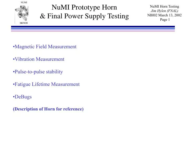
NuMI Prototype Horn & Final Power Supply Testing. Magnetic Field Measurement Vibration Measurement Pulse-to-pulse stability Fatigue Lifetime Measurement DeBugs (Description of Horn for reference). Magnetic Horn General Design Features. Outer Conductor. Stripline. B. Inner Conductor.

E N D
NuMI Prototype Horn& Final Power Supply Testing • Magnetic Field Measurement • Vibration Measurement • Pulse-to-pulse stability • Fatigue Lifetime Measurement • DeBugs • (Description of Horn for reference)
Magnetic HornGeneral Design Features Outer Conductor Stripline B Inner Conductor • Large toroidal magnetic field • Requires large current, 200 kAmp • Thin inner conductor, to minimize p+ absorption • Water spray cooling on inner conductor • Most challenging devices in beam design • Prototype test 1999-2000 to check design p+ I Spray Nozzle Focus p+ toward detector Insulating Ring Drain
Horn Fabrication Precision Welding
Prototype Horn at Test Standupstream bell endcap Features: Anodize outer conductor (corrosion, insulation) Nickel plate inner conductor (corrosion, fatigue)
Horn Power SupplyCapacitor Bank + SCRs Moves as single 11 ton unit Other side looks identical Supplies 205 kA to two horns in series Variable 2 ms to 5 ms half-sin-wave pulse width 1.87 second repetition rate 120 7.5mF caps.
Horn Power SupplySCRs SCRs (3 of 12) Stripline
Horn Power SupplySCRs Charging supply and controls/interlock rack Second charging supply added in series for some cap-bank and pulse-width combos Now using one supply at 860 Volts max. output Problem during operation: on circuit with diodes to protect supply from cap. bank back-feed in case of fault – had to use higher rating component
Horn Field Measurement Main horn field between conductors Field between conductors: a 1/R as expected very symmetrical agrees within meas. error with current
Horn Field Measurement in ‘field-free’ region through center of horn 2% F/N criterion on flux in M.E. beam (approximately scaled to 0.85 ms test pulse from 2.6 ms operational pulse) Measurement with probe moving along horn axis Error or fringe field in “field-free” region down center of horn is so small that no correction should need to be put into the Monte Carlo.
NuMI Horn 1Vibration Measurements Why -Confirm ANSYS modeling so believable horn lifetime estimation. -Horn resonances driven by transmission line, ground vibrations, etc.? -Archival data useful if have a stress/fatigue failure How -Use “laser” non-contact absolute position sensor; eclipseometer. Bandwidth ~ 20kHz. Sensitivity ~ 0.1 nanometer. Measure at upstream inner cond. bell, 205 kA, 850 sec half-cycle, 1.9 sec rep rate. Resonances described by a linear model x = Ai sin(it) exp(-t/i) Resonance Relative Decay Source Freq. (Hz) Amplitude Const. (sec) 1287 -1.0 0.01 Horn Innerconductor 1175 -1.0 0.01 Horn Innerconductor 188 0.05 1.0 Transmission Line 168 - 0.16 0.6 Transmission Line 163 0.16 0.6 Transmission Line -0.30 0.2 Horn Thermal
NuMI Horn 1Vibration Measurement on Horn Bell Endcap (ANSYS gives 71 mm) DATA 6 mm DATA 55 mm 1.17 kHz (ANSYS 1.19 kHz) Linear Model Linear Model 0.03 sec 2 sec
Pulse-to-pulse Stabilitypeak current and field monitor Bdot coil field monitor (sensitive to water temp) I1: Current in Stripline 1 I2 I3 I4 1% 1% Initial warm up about 14 hours of data
Metal Flakes in Horn Specks of metal collected on ceramic insulator at bottom of horn - appears to be Nickel Parts of horn visible through ports, both anodized O.C. and nickel plated I.C, look like new – would have to disassemble horn to locate source of flaking No operational problem noted yet, but indicates water filter important to prevent possible clogged spray nozzles In horn, under water Some flakes removed
Lesson from PrototypeWater line A water line overstressed a feedthrough, which cracked and allowed a drip to develop (The slow leak would not have been fatal to a horn in the NuMI beamline) Have modified the design Old water tube New strain-relieved water tube
Horn and Stripline Afterthought: Unistrut brace between striplines was added to reduce vibration. Brace cracked, has been removed. More noise without brace, but vibration of horn only marginally affected (Temporary temperature probe)
Summary of Test Minor troubles encountered Redesign water line Beef up charging supply snubber circuit Very successful test: Horn has taken 6 million pulses without breaking Magnetic field looks great Vibration matches expectations Power Supply stability is good
General Horn System Parameters Parameter Horn 1 Horn 2 Neck Radius (cm) 0.9 3.9 Wall Thickness, Neck (mm) 4.5 5.0 Outer Conductor Radius to i.d. (cm) 14.9 32.3 Inductance (nH) 685-690 ~457 Resistance (µΩ) 208 (meas.) <112 Average Power from Current Pulse (kW) 17.0 <7.5 Power Flux at Neck (W/cm2) 14.5 <4.7 Temperature Rise at Neck (oC) 22.8 <7.1 * Note: Above heat load numbers are from original design pulse width of 5.2 msec
Mechanical Loading and Analysis Mechanical Loading of Horn is the Result of : - Current pulse thermal expansion from resistive heating (peak at the end of the pulse) - Magnetic forces (peak at the mid-pulse) - Beam heating from particle interaction in material Horn 1 Horn 2 Inner conductor resistive heating 17 kW <7.5 kW Inner conductor beam energy deposition kW 0.4 kW Outer conductor beam energy deposition 14.5 kW 5.4 kW (1” thick) (1” thick) * Note: Above numbers from original design pulse width of 5.2 msec
Mechanical Loading and AnalysisAreas of Highest Mechanical LoadingValues for 5.2 msec Pulse Width • US end cap: minimum stress before pulse is -1030 psi; maximum stress at mid-pulse is -9020 psi; mean stress is -5025 psi with an alternating stress of 3995 psi; Stress ratio R=0.11 • Under the above calculated stress levels, allowable maximum stress for 107 cycles at endcap is 26.5 ksi resulting in fatigue safety factor of 2.9 • Neck of horn: stress at mid-pulse is +4351 psi; stress at end of pulse is -3742 psi; mean stress is 304 psi with alternating stress 4047 psi; Stress ratio R = -0.86 (Note: Negative value of R results in lower value of fatigue stress limit) • Under the above calculated stress levels, allowable maximum stress for 107 cycles at neck is 15.3 ksi resulting in fatigue safety factor of 3.5 • Stress in conductor weldment regions is very low (<<4 kpsi) * Fatigue data from Aerospace Structural Metals Handbook
Corrosion ConsiderationsFactors Affecting Fatigue Life • Moisture reduces fatigue strength • For R = -1, smooth specimens, ambient temperature: • N=108 cycles in river water, smax= 6 ksi • N=107 cycles in sea water, smax~ 6 ksi • Hard to interpret this data point • N=5*107 cycles in air, smax= 17 ksi • The above data is motivation for utilizing corrosion/encapsulating barrier layer over aluminum substrate
HornCorrosion Barrier Layer • I.C.: Electroless nickel: reasonable corrosion barrier properties, non-dielectric, more expensive, limited vendor base with large tank capacity • Conducted fatigue test of nickel coated aluminum samples at the 107 fatigue limit and compared results with equivalent non-coated aluminum specimens: coated samples survived 1.7x 10⁷ cycles, non-coated samples failed at 0.6x 10⁷ cycles • Use high phosphorus electroless nickel (0.0005” - 0.0007” thick) on inner conductor and conductor supports • O.C.: Anodizing: best solution for lower stress thick cross-section areas Type III (hard coat sulfuric acid, 0.0023”), Rc 60-65, dielectric strength of ~800 V/mil • Type III hardcoat anodize is selected for outer conductor and thick lead in portion of inner conductor; not suitable for thinner/higher stress areas of inner conductor due to approximate 60% reduction of fatigue strength • Provides extra protection against I.C. to O.C. short circuit
Horn Fabrication Precision Welding • Single pass, full penetration CNC weld is required to minimizing conductor distortion, assure repeatability, and control internal weld porosity • Proper cleaning, handling, fixtures, and weld parameters are crucial to minimize • conductor distortion and internal weld porosity • NuMI approached welding solution via parallel paths • 1) Identify vendor base to subcontract critical horn conductor welding • - Vendor base for CNC TIG welding extremely limited and expensive; less • flexible fabrication path than in-house • - Prototype horn 1 fabricated in this manner using Sciaky as prime contractor, • ANL as subcontractor • 2) Investigate the development of welding capability in-house • - Have specified, benchmarked, purchased, and commissioned a Jetline fully • automated TIG welding system for producing controlled conductor weldments • - System installed at MI-8 horn facility • - Long term solution for welding 4 initial horns (production and spare horn 1 • and horn 2)
Technical Progress Prototype Horn 1 Design Summary • Conductor Fabrication • Inner conductor fabricated from 6061-T6 billet per QQA 200/8 • Relatively good strength (UTS ~ 45 ksi, YS ~ 40 ksi, R=-1 FS ~ 16 ksi) • Available in variety of sizes and shapes • Welds readily • Relatively good corrosion resistance • All prototype horn inner conductor parts CNC machined by Medco to tolerances better than ~ 0.002” • Inner conductor welding complete - CNC TIG - Overall tolerances held to ±0.010” over 133.375” length (straightness and radial deviation from ideal) • Outer conductor overall tolerances better than ±0.010” • Outer conductor anodized, inner conductor uses electroless Ni coating • Stripline contact surfaces use 0.0005” silver brush plating
Prototype Horn 1 Design Summary • Water Seals • - Total of 64 water seals in horn • - Utilize EVAC aluminum delta seals on KF style flange • Bolted Connections • - Utilize TimeSert threaded inserts, pullout exceeds 9600 lb. on 3/8” insert • - As a reference, maximum end wall reaction is approximately 4270 lb. • Current Contact Surfaces • - Current surfaces have 32 µin finish, 0.0003”-0.0005” silver plate finish • - Interface clamping pressure exceeds 1400 psi • - As reference, lithium lens secondary contact lead is 5.01 in2 for 6285 Arms; • Prototype horn 1 contact area is 9.2 in2 for 7250 Arms. • Corrosion/Erosion Control • - Outer conductor and thick lead in section of inner conductor employs 0.0023” • thick Type III hard coat anodize followed by mid-temp nickel seal • - Inner conductor utilizes 0.0007” thick high phosphorus electroless nickel • Inner Conductor Spider Support Columns • - Design has been experimentally tested to 36 million cycles at defections of ±0.031” • with 80 lbs. axial preload with no failures