Download
1 / 10
100 likes | 479 Views
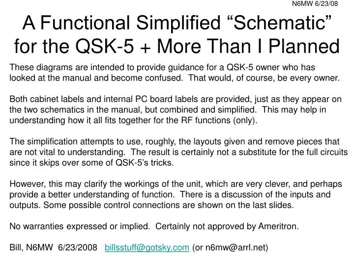
A Functional Simplified “Schematic” for the QSK-5 + More Than I Planned. These diagrams are intended to provide guidance for a QSK-5 owner who has looked at the manual and become confused. That would, of course, be every owner.

E N D
A Functional Simplified “Schematic” for the QSK-5 + More Than I Planned These diagrams are intended to provide guidance for a QSK-5 owner who has looked at the manual and become confused. That would, of course, be every owner. Both cabinet labels and internal PC board labels are provided, just as they appear on the two schematics in the manual, but combined and simplified. This may help in understanding how it all fits together for the RF functions (only). The simplification attempts to use, roughly, the layouts given and remove pieces that are not vital to understanding. The result is certainly not a substitute for the full circuits since it skips over some of QSK-5’s tricks. However, this may clarify the workings of the unit, which are very clever, and perhaps provide a better understanding of function. There is a discussion of the inputs and outputs. Some possible control connections are shown on the last slides. No warranties expressed or implied. Certainly not approved by Ameritron. Bill, N6MW 6/23/2008 billsstuff@gotsky.com (or n6mw@arrl.net)
RF In KA1(to AMP RELAY) ANT KA2 L “RLY” TX Pin RX Pin TX Pin A fuse lamp H AMP OUT F KEY1 Controls Relays KEY2 Controls TX/RX PIN diode switching with keying F A AMP IN “RLY1” AUX output XCVR OUT INPUT OUTPUT AMP XCVR RF (ONLY) FUNCTIONAL CONNECTIONS (RELAYS SHOWN OFF)
RF In KA1(to AMP RELAY) ANT QSK-5 STEADY STATE RX MODE AND QSK-5 BYPASS MODE KA2 L “RLY” TX Pin RX Pin TX Pin A fuse lamp H AMP OUT F Note that AMP RELAY would normally provide an amplifier bypass by a line to the amplifier internal relay. Otherwise there is no RX path through the amp. KEY1 Controls Relays KEY2 Controls TX/RX PIN diode switching with keying F A AMP IN “RLY1” AUX output XCVR OUT INPUT OUTPUT AMP XCVR KEY1 NOT GROUNDED (IN LAST 3 SEC) OR QSK-5 OFF - SIGNAL PATH
RF In KA1(to AMP RELAY) ANT KA2 NORMAL QSK-5 TRANSMIT L on “RLY” on off TX Pin RX Pin TX Pin A fuse lamp H AMP OUT F These lines, including AUX, follow the keying TX SIGNAL PATH Note it does not go through the fuse lamp KEY1 Controls Relays KEY2 Controls TX/RX PIN diode switching with keying F A AMP IN “RLY1” AUX output XCVR OUT INPUT OUTPUT AMP XCVR QSK-5 ON, KEY1 ON (GROUNDED) KEY2 ON (KEY DOWN)
RF In ACTIVE QSK RECEIVE BEFORE 3 SEC DELAY IS OVER KA1(to AMP RELAY) ANT KA2 L off “RLY” off on TX Pin RX Pin TX Pin A fuse lamp H AMP OUT F RX SIGNAL PATH KEY1 Controls Relays KEY2 Controls TX/RX PIN diode switching with keying F A AMP IN “RLY1” AUX output XCVR OUT INPUT OUTPUT AMP XCVR QSK-5 ON, KEY1 ON (GROUNDED, AT LEAST IN LAST 3 SEC) KEY2 OFF (KEY UP)
What Outputs from my Break-In XCVR are Needed? For CW you need to select the full (or maybe fast semi-) break-in capability (sometimes called QSK mode) to make the QSK-5 worthwhile. Most modern XCVRs have this feature. The one required XCVR output is an (expanded) replica of the on/off morse keying signal that goes low for the key down periods. This line comes by many (often confusing) names. These include QSK line, TX OUT, amplifier control relay, KEY-OUT, SEND, RELAY, TX-GND, EXT T/R, …, that is normally used to control an amplifier T/R switch. Sometimes this is from a XCVR relay but often from a solid state switch. The signal on this line is an “expanded” keying replica to assure that there is enough time between the line going low so the PIN diodes and any relays can change to TX state before RF is applied. The extent of the expansion is usually imposed only by fixed timing (often ~ 10 ms delay) but this may be adjustable for some XCVRs. The timing at the end of key down is important also since the PIN diodes should not return to the RX state until the RF flow is finished. Timing errors on either end will be indicated by flashing fuse bulbs (until they burn out and stop flashing). Typically this “QSK line” with its many possible names serves as the amplifier relay control line in all the modes, not just CW. In this case, no addition control lines may be needed to operate SSB or other modes. However, if this is not true, you might need a separate VOX or PPT line or amp relay control for other mode control that goes low on transmit. I know of no specific cases for any XCVRs where this is required. TheTS-570 does not need it. But depending on the timing of the VOX line, you might get a timing jump benefit over the QSK line even if VOX does not appear to be needed. Finally, some modern TenTec units, and maybe others, have a QSK “keying loop” that allows transmitting system elements downstream of the XCVR to provide feedback to the XCVR for TX Enable/Inhibit functions that should assure no hot switching without relying on raw timing. For example, TenTec explicitly calls for the use of this line (although here it appears to just be a trick to fool the XCVR in this case, offering no real protection). So, mostly, you will just need a single, well chosen, control line from the XCVR.
So what part of Figures 2a, 2b and 2c don’t you understand? • Ignoring the RF part of the hookup shown before, the RCA jacks on the QSK-5 rear panel have 2 outputs and 2 inputs that are for control. These are: • AMP RELAY (output) – this line is grounded internally in the QSK box when QSK-5 is in TX mode and normally stays grounded until 3 seconds after the end of a transmission. The intention is run to a cable from here to the relay jack on your amplifier. So if your amplifier relay is activated (switched from bypass to amp IN LINE) by grounding, you are golden - unless, of course, you exceed the rating of maximum pull down of 25V(+only) with a 1 amp current draw. Some older amps are a problem here. • AUX (output) – this line follows the KEY2 line with ~ 1 ms delay for initiation, going low on key down. It has two quoted uses: 1) It can provide a “handshake” or TX Enable/Inhibit signal back to the XCVR (not required for many XCVRs) indicating the QSK box is now ready for RF to begin since the TX PIN diodes have had time to be activated; AND/OR 2) to pass the KEY2 signal to KEY1 with a simple cable, but with the 1 ms delay. (This delay is not a good thing here but it is probably too short to matter.) • KEY2 (input) – this line needs an expanded replica of the off/on morse keying signal that follows the actual keying of the XCVR, typically from some auxiliary port. This keying line from the XCVR is called the “QSK line” by Ameritron. Key down should pull the level to ground. The signal on this line is not an exact replica of the keyer but one that expands the key down times to begin a little earlier and end a little later. This morse keying line does not modulate the signal in the QSK box but is just used to define the switching times between the TX and RX PIN diodes. About 1 ms is needed to switch the PIN diode TX/RX state. • KEY1 (input) – NORMAL USE with QSK box ON. When KEY1 is line pulled to ground, the two QSK internal relays are actuated providing RF access to the QSK PIN diodes. This also pulls the AMP RELAY line to ground so if it is connected to an amp, KEY1 also can switch the amp to IN LINE. Once KEY1 is activated, the two QSK relays will be continuously closed until KEY1 ceases to be activated and approximately 3 second have elapsed. • KEY1 Actuation Methods: • Connect an RCA jumper from AUX to KEY1. Due to the 3 second release delay, KEY1 when activated, will hold the relays closed on the first key down time, but after a delay of ~ 1 ms. • Connect KEY1 to the PPT or VOX or QSK line from the XCVR (maybe in addition to 1) ). • 3) Ground KEY1. If this is not switched, the amplifier may always be in the IN LINE mode and drawing idle plate current unless you have another switching arrangement that comes after AMP RELAY.
So what part of Figures 2a, 2b and 2c don’t you understand? KEY1 (input) – ATYPICAL USE with QSK box OFF. When OFF, the two QSK relays will not close and the KEY2 input will not have any effect so you will not get QSK. However, IF you are applying a PTT/VOX/AmpRelayControl signal directly to KEY1, that will activate the AMP RELAY circuit. This does NOT mean that you can operate CW business as usual unless you like to listen to your amplifier relays following your CW signal with, possibly, hot switching in the amplifier relay contacts, depending on the timing. You might get away with semi-break in – but why would you do that? SOME CAUTIONS: Fuse Lamps – If these bulbs flash during transmission, that is a bad thing indicating RF timing problems. Although the “manual” suggests in the AMP RELAY section that you can actuate the AMP RELAY line using KEY2 (but with a delay), what they (surely?) mean is if you activate the AMP RELAY with KEY2 using the jumper from AUX to KEY1 you get the delay. In fact, if KEY1 is not connected, you cannot actuate the AMP RELAY line by KEY2. Timing is everything - hot switching concerns. This QSK unit never changes its state (On/Off, relays open/closed, RX or TX PIN diodes active) in any way that depends on the actual RF flow. It responds only to the timing of the KEY1and KEY2 inputs and mechanical (relays) or electrical circuit elements. However, the most critical timing is the XCVR timing on initial key down between the initiation of the signal (which goes to KEY2) to close the amp relay and switch PIN diodes to TX and the beginning of RF emissions from the XCVR. For example, for the Kenwood TS-570 in full break in, this delay is claimed to be 10 ms. The QSK-5 unit requires ~ 1 ms to get ready for TX by biasing the TX PIN diodes. When the initial signal to KEY2 appears, there is thus a ~ 1 ms delay before the AUX output goes low, triggered on verification of the PIN diode TX state. If this AUX signal is used to activate KEY1, all the relay closures are initiated at that time. Typical relevant relay closure times appear to be the order of 10 ms. So in this case it might be a close thing as to whether the key closures will beat the arrival of RF. So there may be some danger of hot switching in the relays even though the TX PIN diodes are easily set up in time. Hot switching of the relays will not cause flashing fuse bulbs. This is one reason that it may be good to avoid relays, if possible.
Is Blocking Diode Hell Required? Some Possible Hookups (only control lines shown) with no Keying Loop . A. Standard B. Standard, no amp control needed KEY1 KEY2 AMP RELAY KEY1 KEY2 XCVR QSK line AMP RELAY XCVR QSK line AUX AUX to amplifier relay jack C. Standard, if you simply MUST have a diode D. Amp always ON LINE (if QSK-5 ON) KEY1 KEY2 KEY1 KEY2 AMP RELAY AMP RELAY XCVR QSK line XCVR QSK line AUX AUX to amplifier relay jack to amplifier relay jack This is the configuration in use at N6MW where a subtle feature of the QSK-5 is used to kill the idle current (I and J terminals for bias switching), as briefly mentioned in the manual. Details in a 2007 posting to Contesting/AMPS.
So what’s with Figure 2, Ameritron QSK-5 Manual? 2a. This is a version of the previous “A” connection, which TenTec Support points to, with diode, as the desired hookup for their modern XCVRs (but without the VOX line) using a keying loop – “QSK line” input from TX IN and the handshake going to TX EN. Either the VOX line or the AUX line will pull down KEY1, depending on which goes low first. If the QSK-5 is OFF, the VOX line will activate the AMP RELAY with no delay and with no release delay. 2b. This is a version of the previous “C” connection with the handshake line made available and the AUX connected to KEY1 just because it can. 2c. (not shown) “What??” - quoting David Letterman