Download
1 / 45
470 likes | 811 Views
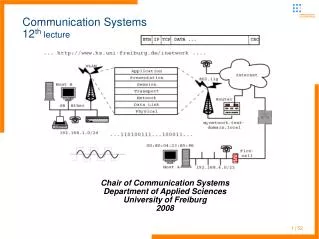
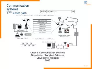
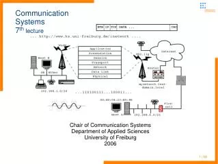
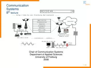
Chair of Communication Systems Department of Applied Sciences University of Freiburg 2006. Communication Systems 9 th lecture. 1 | 45. Communication Systems Administrative stuff / Last lecture – introduction to telephony networks. 15.06 is holiday, no lecture, no practical

E N D
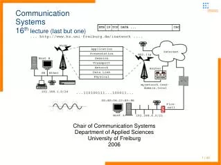
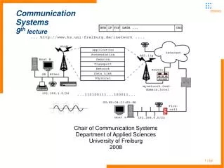
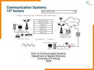
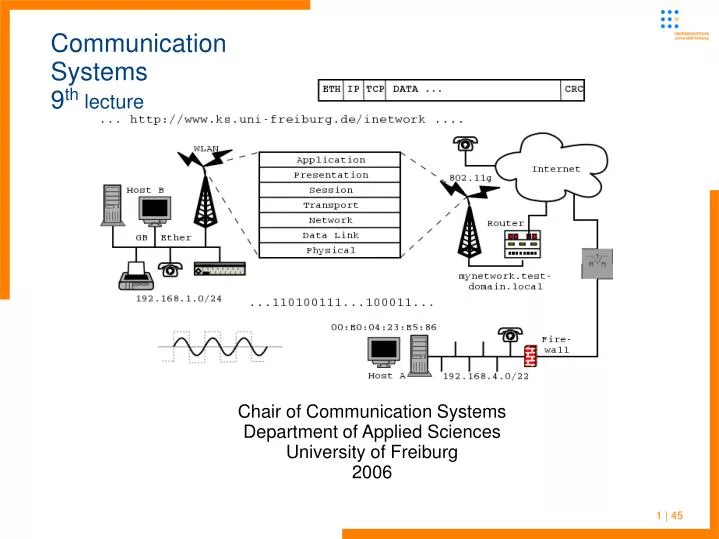
Chair of Communication Systems Department of Applied Sciences University of Freiburg 2006 Communication Systems9th lecture 1 | 45
Communication SystemsAdministrative stuff / Last lecture – introduction to telephony networks • 15.06 is holiday, no lecture, no practical • Telephony networks rather old communication infrastructure • Invention of the telephone in the late 19th century • First manually switched, later on mechanical automatically switched networks • Inband dial signaling first with pulses later on with DTMF (to handle other media than copper wire too) • Completely other concepts to handle standardization, protocol and definition of interfaces (than in the IP world) • Computerized switching centers and the introduction of ISDN in the 1980s 2 | 45
Communication SystemsLast lecture – introduction to telephony networks • ISDN – Integrated Services Digital Network • First fully digital telephony network • PCM for voice digitization • BRI offers two B channels (64kbit/s for either voice or data communication) and a separate D channel for out of band dial and control signaling • D channel are defined in the 3 lower OSI layers – physical interface with different encodings, e.g. 4B3T • DLL represented by LDAP protocol • DSS1 is handling call setup, signaling, call destruction, gives information on caller ID, ... 3 | 45
Communication Systemsplan for this lecture • Signaling in large scale digital networks • Last lecture – signaling between terminal endpoints (TE) and the local switching center • Primary Rate Interface • But how is a call setup and routed globally • Signaling system #7, MTP, SCCP, ISUP • QSIG for inter-connecting PBX • First introduction to mobile telephony networks and GSM. 4 | 45
Communication SystemsPrimary Rate Interface - PRI • Talked on ISDN Basic Rate Interface (BRI) last lecture • Enough for average household or small office • But insufficient to serve larger enterprises and organizations • Primary Rate Interface (PRI) handles large scale connectivity • ITU-T specifications G.703, G.704, G.705 • includes 30 B channels (each B channel 64kbit/s), a full rate D channel at 64kbit/s and a framing/synchronization pattern (64kbit/s) • Channels could be bundled, so called H channels: H0 384kbit/s, H11 1534kbit/s and H12 1920kbit/s 5 | 45
Communication SystemsPRI – physical specification, interfaces • Brutto bandwidth sums up to 2.048kbit/s connection • Copper wire connections allow up to 250m without refresh, for longer distances often fiber optics is used • All connections are unidirectional, so no channel separation is needed as was in BRI • Name of the interface from switching center: UK2 , for fiber optics: UG2, user interface is named S2M • Different channels transmitted in TDM (Time Division Multiplexing) • International E1 (European ISDN standard) systems use HDB3 (High Density Bipolar 3) line coding 6 | 45
Communication SystemsPRI - HDB3 line coding • Two kinds of transmission media used to transmit E1 signals • coaxial cable (2,37V peak base) • twisted-pair cable (3V peak base) • HDB3 Line Coding is similar to AMI coding • To avoid co-current flow strings of 4 zeroes are replaced with one of four bipolar violation codes, example for 8 consecutive zeros 7 | 45
Communication SystemsNetwork signaling • Of course there are options to bundle more than 30 channels into a site connection – other media, e.g. fibre optics is used then (underlying transport technology is often ATM – Asynchronous Transfer Mode) • In BRI and PRI connections a separate channel is used for signaling D / DSS1 multiplexed into the same physical connection • In modern large scale telephony networks signaling and real connections are completely independent • Connectivity between switching centers is handled by a specialized signaling system – Signal System Nr. 7 (SS7) 8 | 45
Communication Systemsindependent networks for signaling and connection • Signaling layer consists of Signaling Points (SP) and Signaling Transfer Points (STP) 9 | 45
Communication Systemsline switching and signaling network • Signaling layer is a virtual layer ontop the connection layer network (coupling network) • SP's are the direct involved switching centers of a connection, STP just route signaling information • End points of a connection are the the end switching centers where the subscribers are connected to • Every switching center should be connected at least to two STP for backup • Thus route optimizations and fallback routes implemented • Signaling data itself is transported in usual bearer channels (B channel) of the connection layer of the switching centers 10 | 45
Communication Systemsline switching and signaling network • Signaling network uses a network indicator to distinguish different networks • SP use a Signaling Point Code of 14bit and could be associated with up to four networks • This allows changeovers between different networks • For international connections special ISTP (International Signal Transfer Points) are operated • SS7 is specified in ITU Q.700 recommendation • Resembles the OSI 7-layer model because mostly packet orientated operation • Major distinction of protocol levels is made into transport and application part 11 | 45
Communication SystemsSignaling System 7 • SS7 does not conform exactly to OSI • Primarily made not for direct user data exchange but telephony network specific information 12 | 45
Communication SystemsSignaling System 7 – layer 1 • Layer 1 defines the (physical) access to the coupling network • Protocol name: MTP (Message Transfer Part) specified in in ITU G.701-710 • Defines a bi-directional signaling link • Uses the standard 64kbit/s connections • In PRI normally channel 16 is defined for that purpose 13 | 45
Communication SystemsSignaling System 7 – layer 2 • Layer 2 main task is frame synchronization (more tasks compared to OSI data link layer) • Distinction of blocks (signal units) through flags • Flag consists of 8 bits: 0111 1110 • Securing of block ordering via numbering • Transparent transmission • Flow and congestion control • Error detection with the help of checksums in every signal unit • Error correction through retransmission and acknowledgements – preventive cyclic retransmission and ARQ 14 | 45
Communication SystemsSignaling System 7 – layer 2 • There are three different message types • Message Signaling Unit (MSU) is meant for transmission of standard signaling information • Link Status Signaling Unit (LSSU) transmits detailed information on the current status of the signaling link • Fill-in Signaling Unit (FISU) – synchronisation if no signaling information is transmitted - kind of “keep-alive” 15 | 45
Communication SystemsSignaling System 7 – layer 3 • Layer 3 composed of MTP and SCCP • Decides if a message is to be routed or not • General routing decisions for signaling messages • Distribution of messages to application layer (different types of user parts) • Network management and monitoring • Four types of messages • MTP management information • Messages for the Telephone User Part (TUP), ISDN User Part (ISUP) • SCCP (Signaling Connection Control Part) messages 16 | 45
Communication SystemsSignaling System 7 – layer 3 • All messages contain Destination Point Code (DPC) and Origination Point Code (OPC) (comparable to addresses in TCP/IP) • Routing in SS7 follows these principles • Minimal pathes, pass minimum number of SP, STP • If more then one link, distribute load equally • Every signaling information should take the same path • The Signaling Link Selection (SLS) is for load balancing • All messages with same SLS are sent through the same channel 17 | 45
Communication SystemsSignaling System 7 – layer 3, SCCP part • SCCP is an extension to MTP for OSI conformance, defined in Q.711-716 • Transports ISUP and TCAP messages • End-to-end routing (MTP handles the hop-to-hop routing) • Extends the Signaling Point Code for GT (Global Title) addressing • GT is worldwide unique for international routing of signaling information • SCCP defines four protocol classes: class 0: connection less transmission, segmentation (max. 16), distribution of messages over several signaling links 18 | 45
Communication SystemsSignaling System 7 – SCCP protocol classed • SCCP defines four protocol classes: class 1: connection less, keeps sequence of messages, same SLS code (no load distribution) class 3: simple connection orientated transmission, end-to-end, flow control class 4: connection orientated, option to bypass flow control, end-to-end connection • There are several message types defined for the different classes 19 | 45
Communication SystemsSignaling System 7 – layer 4-7, application layer protocols • Transaction Capabilities Application Part (TCAP) defined for the services of the “Intelligent Network” (IN, advanced network for management, configuration and mobile telephony services) • Message exchange through structured or unstructured dialogs for several actions within network • TUP and DUP are the old style User Parts for non ISDN telephony and data • The ISDN User Part (ISUP) handles the ISDN signaling stuff • End-to-end, so that intermediate switching centers do not have to decode signaling information 20 | 45
Communication SystemsSignaling System 7 – ISUP • ISUP is used for: • Setup and destruction of B channel connections • Handling of signaling of the several ISDN characteristics (call deflection, call on hold, conference, ID signaling, ...) • Connection of different logical connections, e.g. when passing network borders (international connections) • ISUP consists of a header, required parameters of fixed length, required parameters of variable length and optional part 21 | 45
Communication SystemsSignaling System 7 – ISUP • Header contains • Routing label for all signaling messages needed by participating switching centers (OPC, DPC, ...) • Circuit Identification Code for addressing of a certain B channel used • Message type defines the kind of signaling and message format • Construction of body (the parameters are the message) differs dependent of the message type • End octet: 0000 0000 22 | 45
Communication SystemsSignaling in private branch exchanges • The telephony providers often do not handle internal communication of (large) firms, organizations, ... • They use private branch exchanges (PBX) under their own jurisdiction • Digital PBX are connected to the public network most commonly via ISDN BRI or PRI interfaces • Internally they use not SS7 but DSS1 (D channel protocol) in small scale exchanges and QSIG in large scale PBX • Q.931 protocol was intended to be used for signaling within PBX but every manufacturer created his own protocol (there is much money in the market and thus much interest that a customer does not uses different equipment) 23 | 45
Communication SystemsSignaling in private branch exchanges • QSIG was specified by the ECMA (European Computer Manufacturers Association) • Q in the name refers to the Q reference point in the PBXs • At layer 1&2 QSIG is identical to the DSS1 EURO ISDN protocol • The layer 3 is split into three sublayers: Basic Call (BC), Generic Function (GF) Protocol and QSIG Procedures for Supplementary Services (SS) • BC implements ISDN standard functionality, GF should allow the inter-connect of devices of different vendors, SS allows for transparent services extensions (automatic call completion, display of tolls, ...) 24 | 45
Communication Systemsmobile telephony networks - history • With the development of digital telephony networks and defined signaling standard between switching centers the preconditions for digital mobile telephony were met • First mobile phone networks started around end of 1940s in the US • St. Louis, Missouri, single cell system • “A-Netz” in Germany operated from 1957 to 1977 • Analogous network in the frequency range between 156MHz and 174MHz • 15 manually switched channels (in the final version over 100 wireless sector areas with together over 300 channels) 25 | 45
Communication Systemsmobile telephony networks – German A-Netz • 50 kHz distance between channels • Use of frequency modulation • 10.500 participants • Mostly used in cars (size!!) • Main problems were the manual operation, no automated handover when moving and limited possible number of participants 26 | 45
Communication Systemsmobile telephony networks - history • The deployment of German B-Netz started in 1972 and was the automated successor of the A-Netz • Main advantage: calls could origine both in the mobile and the wired network – but for calling a B-Netz participant you had to know the area (diameter of 27km) where located • The old federal republic was split into 150 zones with a diameter of up to 150km (a zone could host more then one base station) • Frequency ranges 148,4 MHz - 149,13MHz and 153,0MHz - 153,73MHz, later 157,61 MHz -158,33MHz / 162,2MHz -162,93MHz 27 | 45
Communication Systemshistory – B1/B2 mobile network • B-Netz, B1/B2 net from 1982 • Offered 38 voice channels up to 1980 • 75 channels after recycling of the A-Netz frequencies • Bandwidth per channel 14kHz, channel distance of 20kHz • Frequency modulation with a 4kHz frequency deviation • The network even offered a limited roaming with Austria, Luxemburg and the Netherlands • In the beginning 16.000 participants, after the extension 27.000 participants would be the maximum • Peak usage was in the middle of the 80s: 850 frequency channels and 158 base stations 28 | 45
Communication Systemshistory of mobile telephony networks – cellular networks • Main problem of the analogous networks was the limited number of participants • Challenge was how to accommodate much more users within a mobile phone network • Cellular concepts were developed and tested from the late seventies: technology advances enable affordable cellular telephony • entering of the modern cellular era started 1974-1978 with first field Trial for Cellular System by AMPS in Chicago • Cellular concepts reuse frequencies and do not try to use the same frequency over a wide area (to avoid handovers of moving participants) 29 | 45
Communication Systemshistory of mobile telephony networks – cellular networks • First generation of digitally switched mobile networks started in the 1980’s • Several competing standards in different countries • NMT (Nordic Mobile Telephone) scandinavian standard; adopted in most of Europe • First european system (Sweden, 1981) • TACS (Total Access Communication Systems), starts in 1985 • UK standard; A few of Europe, Asia, Japan • AMPS (Advanced Mobile Phone Service) • US standard 30 | 45
Communication Systemshistory of mobile telephony networks – cellular networks • Radiocom 2000 (Only in France) • Analog transmission of voice (no data services) using frequency modulation • Various bands were defined in different countries, areas: • NMT: 450 MHz first, 900 MHz later • TACS: 900 MHz and 1230 bidirectional channels (25KHz each) • AMPS: 800 Mhz • Most of the first generation mobile networks are switched of, but the frequencies still partly in possession of the several network operators (new services like “Wireless DSL” ...) 31 | 45
Communication Systemsfirst generation cellular networks - C-Netz in Germany • C-Netz in Germany (used too in Portugal and South Africa) started in 1985 and offered a lot of advantages • Common prefix: 0161for all participants • Interruption-less handover between cells • Scrambling of the analogous radio signal exacerbated the eavesdropping of connections • Not only car systems but real portable devices • “huge" capacity of up to 850.000 participants in Germany • Frequency range 451-455,74MHz, 461-466,74MHz • Operated up to the 31th of December 2000 32 | 45
Communication Systemscellular networks - planning • Planning of cellular networks is a complex procedure • cover the same area with a larger number of base stations (BS) • Partitioning of an area into radio cells idealized as hexagons, the hexagon is a rather good approximation of a circle • Frequency channels could not be reused in neighboring cells because of interference • modelling: setup of clusters • Cluster contains: k cells, which use together the complete frequency range • k size of the cluster 33 | 45
Communication Systemscellular networks - clustering of areas • Cell radius will differ in size depending on expected density of users • Real coverage of a cell is often different from idealized mode • Ideal coverage pattern would generate no holes and no cell superposition 34 | 45
Communication Systemscellular networks - planning • Example of cluster size 3 • Generic formula k = i² + i*j+ j² • Thus cluster sizes of 1, 3, 4, 7, 9, 12, 13, 16, 19, 21, ... are possible • With decreasing of cluster size the capacity of the network increases • But the interference will increase (tradeoff) 35 | 45
Communication Systemscellular networks of second generation • General formula for reuse distance: D=R * sqrt(3K) • Valid for hexagonal geometry • D = reuse distance • R = cell radius • q = D/R = frequency reuse factor • For the example k=3, the reuse factor is 3, for k=12 is 6 • Frequency reuse implies that remote cells interfere with tagged one • Co-Channel Interference (CCI) • Sum of interference from remote cells • For computation see literature 36 | 45
Communication Systemscellular networks of second generation • Four systems in use today • Global System for Mobile Comm. (GSM) • Digital AMPS (D-AMPS), US • Code Division Multiple Access (IS-95) – Qualcomm,US • Personal Digital Cellular (PDC), Japan • GSM by far the dominant one • Originally pan-european • Deployed worldwide in around 200 countries (even in countries without any working administration), more then 500 mobile operators • By now available in US too 37 | 45
Communication Systemscellular networks of second generation – GSM history • 1982 the “Groupe Speciale Mobile” was founded by the CEPT (Conference Europeene de Postes et Telecommunication) to develop a common standard for european mobile networks of the second generation • With the increasing popularity of the GSM standard worldwide, the name was changed to Global System for Mobile Communication • 1987 introduction of the transfer method which is still in use today (with sligth modifications) • 1991 first testbed networks started in 5 European countries • 1992 the two so called D-Netze in Germany started (“D” as the successor of the C-Netz) 38 | 45
Communication Systemscellular networks of second generation – GSM history • Other than in the monopoly wired world in many countries started competing providers of the new services • First variant of GSM operated in the 900MHz (890-915MHz for uplink and 935-960MHz for downlink) frequency band available most countries in Africa, Asia, (partly the US), Europe, Australia • 1993 one Million participants in Germany • 1993 a secondary frequency band of 1800MHz (DCS1800) was defined (1710-1785MHz up, 1805-1880 MHz down) • 1995 completion of so called Phase2 of GSM with the introduction of new features like fax transfer, extended cell choosing mechanism, ... 39 | 45
Communication SystemsGSM – services and applications • As GSM was developed on the core of IN (Intelligent Network) and ISDN, so it inherited a list of features like • Tele- and bearer services like voice and data (SMS, MMS, Internet, Fax…) services • “comfort” services like call deviation and deflection, caller ID, automatic call back on busy, blocking of numbers (outgoing and incoming) • Additional services like telephone answering machines (“Mailbox”, several information desks on Hotels, itineraries, traffic congestion, ...) • Location based services, e.g. for emergency calls, area dependent tolls (O2 “homezone” and other similar offers), area dependent tourist information, navigation, tracking of containers and fright trucks 40 | 45
Communication SystemsGSM – subsystem hierarchy • A mobile switching center (MSC) not much different from a normal switching center handles several location areas MSC region -> N Areas -> M BSC -> K BTS -> I MS with: N < M < K << I 42 | 45
Communication SystemsGSM – subsystem hierarchy • A Location Area (LA) is covered by some BTS (Base Transceiver Station) which are managed by some fewer BSC (Base Station Controllers) • Thus a provider of about 15 Million subscribers (which are using Mobile Stations (MS, simply the mobile phone equipped with a SIM card) will have to setup up to 30.000 radio cells • The cells are covered by up to 12.000 BTS, which are operated by some hundred BSC, which are handled by up to 50 MSC • The MSC uses the services of a Visitor Location Register (VLR) holding copies of user data from the Home Location Register (HLR) 43 | 45
Communication SystemsGSM – subsystem hierarchy • The Home Location Registers operated by each provider is the place where subscriber information is kept • Which services (voice, data, fax, roaming, ...) the user is subscribed to • Data is copied temporarily to VLR where the MS of a user is registered • The Authentication Center keeps the user access and authorization information • The Equipment Identification Center keeps track of mobile equipment (unique serial of Mobile Terminals (MT) – the MS without the SIM) • The mobile network is supervised by the Operation and Maintenance Center 44 | 45
Communication SystemsISDN, IN, GSM literature • E. Pehl, Digitale und analoge Datenübertragung • ISDN http://www.ks.uni-freiburg.de/download/papers/telsemWS05/ISDN/seminararbeitBorstHartges.pdf • ISDN II http://www.ks.uni-freiburg.de/download/papers/telsemWS05/ISDN-erweitert/seminarbThurner.pdf • GSM http://www.ks.uni-freiburg.de/download/papers/telsemWS05/G2-GSM/HA_GSM2_Mohry_1.pdf 45 | 45