Download

1 / 54
560 likes | 780 Views
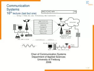
Chair of Communication Systems Department of Applied Sciences University of Freiburg 2008. Communication Systems 9 th lecture. 1 | 54. Communication Systems administrative stuff (lectures and exercises) . Please hand in the theoretical exercise sheets #4

E N D
Chair of Communication Systems Department of Applied Sciences University of Freiburg 2008 Communication Systems9th lecture 1 | 54
Communication Systemsadministrative stuff (lectures and exercises) • Please hand in the theoretical exercise sheets #4 • And grab the new sheet (#5) due for the 24th of June • 16th and 20th are lectures (all held here in this lecture room), next practical course is 24th (again at the computer center, exact start time will be announced the lecture before) • You might refer to the • electures.informatik.uni-freiburg.de for the lecture recordings and slides in different formats • www.ks.uni-freiburg.de for details on upcoming lectures and material like the slides of the practical course (containing the “master” solutions to the exercise questions and some hints for the actual exercise sheets, the requirements on this lecture available from the first practical courses slide set) 2 | 54
Communication Systemslast lectures • Lecture started with rather modern communication technologies and introduced the Internet Protocol as a global orientated packet switching network technology • IP can be run over very different physical media and intermediate protocols • and IP is used for more and more networked services • future IPv6 will solve any address scarcities • Very popular traditional service is telephony mostly 1:1 voice communication • with the more and more widely introduced “Voice-over-IP” we could observe a merge of both networks • and we will see a role change in the sphere of network providers (telephony companies vs. IP services providers, (TV) cable networks) 3 | 54
Communication SystemsUpcoming lectures • To get an idea how traditional and modern wireless telephony networks work, we give an introduction to ISDN, GSM and UMTS • First traditional telephony networks its history and their concepts in general • Components of (digital) telephony networks • Digitization of voice - PCM • Then introduction to ISDN – a completely digitalized communication infrastructure • call setup and global routing in telephony networks • network definitions and standards 4 | 54
Communication Systemsplan for this lecture • History of telephony networks and wireless information networks • Line switching • DTMF – dual tone multi frequency as traditional signalling source • Telephony protocol • Standards in telecommunication • Digital telephony networks – from analogous source to digitized data streams - PCM • ISDN – Integrated Services Digital Network • D channel protocol • DSS1 layer 3 protocol 5 | 54
Communication SystemsHistory of telephony networks • Traditional analogous telephony networks • 1848: State Telegraphy System in Prussia (Siemens) • 1851: First trans-sea cable between Dover and Calais • 1858: Transatlantic line-based telegraphy between Europe and America • 1866: Durable transatlantic cable • 1876: Bell patents the “phone” (Reiss in Germany – you will find even more inventors of the telephone, for each nation one :)) • 1880: 50.000 participants in US phone network • 1881: Berlin opens the first “Fernsprechamt” 6 | 54
Communication SystemsHistory of wireless information networks • Wireless signal transmission • Morse codes transmitted by radio (Marconi) • 1901: Radio-based telegraphy between Europe and the US • 1914: Introducing the teletype/telex system • 1915: Wireless telephony NY – San Francisco • 1920: First public radio transmission in Königs-Wusterhausen • 1923: Start of entertaining radio in Berlin • 1929: First radio-based TV transmission (Funkausstellung in Berlin) • 1935: First regular public TV transmissions in Berlin 7 | 54
Communication Systemsdevelopment of telephony equipment • Traditional analogous telephony networks provides most of the standards (partly) in use up to now • bi-directional voice channel • bandwidth to carry voice around 300Hz - 3,4kHz – just the characteristics of the end user devices and their microphones and earpieces • you could hook up the old mid-thirties or sixties telephone set to your wall socket of your telephony provider or your private telephone installation • end devices are power supplied by the telephone exchange, so the devices independent of local (power) sources (which have some advantages in cases of power failures) 8 | 54
Communication Systemsdevelopment of telephony equipment • Local loop – connection of the end uses device to the telephony exchange • Device is without power when hook on cradle • Call information is signalled with 65V alternating current • When off-hook power supplied at around 60V by a current of 20 – 40mA • Dial plate cuts the local loop for well defined periods to indicate dial information (~60ms cut, ~40ms closed in between – try to dial via cradle – system is rather robust in detection :-)) 9 | 54
Communication Systemsline switching • End systems has to be connected somehow to each other • In the early beginnings manual switch boards (you know the pictures of old films with young ladies called operators plugging wires to connect subscribers :-)) • around 1975 10 | 54
Communication Systemsline switching • Switch boards • first direct-dial switch boards appeared around 1900 used in local area nets first and from around 1920 for long distance calls – dial plates (digits 1 – 9, 0) where added to the telephone device • using special relay boards with contacts for each dialed digit • system operated directly controlled until around 1960s • there is an impressive collection of old (mechanical) switchboards in the Nuremberg Communication Museum 11 | 54
Communication Systemsline switching and signalling • Early phones used a hand generator to signal assistance by the operator at the switch board • Now: Identification of each end device through numerical ID composed of digits from decade system • dial plates (digits 1 – 9, 0) where added to the telephone device 12 | 54
Communication Systemsautomated line switching • Switch boards - routers in the telephony world • major drawbacks of this concept • route of the call is fixed • every dialed digit switches the next relay in the switching network • the (long distance) line was already occupied during call setup (=expensive for the telephone companies, especially if no-one answered the call) • Next step was introduction of indirectly operated switching networks middle of the fifties • before routing setup the dial information was collected and then processed 13 | 54
Communication Systemsline switching • Analogous electronic switching networks appeared with the beginning of the 1970s • allowed new type of dial indication • DTMF – dual tone multi frequency was introduced for dial information • inband signalling • pulse dial information has to be transported via copper wires and require rather high currents • puls dialing impossible over very long distances (resistor capacity of wire) and wireless transmission • major speedup for dialing (same amount of time spent for each digit transmitted) 14 | 54
Communication SystemsDTMF • voice frequency band to the call switching center – frequencies selected in a way that no clash with “normal” voice • multifrequency shift keying (MFSK) 15 | 54
Communication SystemsDTMF signalling • still in use on analogous lines and for signaling e.g. on voice menu systems – digital equipment uses out-of-band • special codes for signaling other data (e.g. Pay card identification) and for cost signaling between switching centers • some people were able to produce the needed frequencies to switch off payment or setup special connections (no cost, used by Telcos for maintenance) • “hacking/cracking” started not with computer networks but with automated telephony equipment – challenge of the 1970s was to setup connections/routes around the globe to call someone other in the same city (and enjoy the delay because of the huge distances) 16 | 54
Communication Systemstelephony protocol • Key dials were introduced to telephones – special optimized layout (in contradiction to keyboard, counters layout used today) • So we have a well known “protocol of analogous telephony connection” 17 | 54
Communication SystemsProtocol of analogous telephony connection 18 | 54
Communication Systemsstandards in telecommunication • But in telephony world mostly not talked on “protocols” but interfaces • Interfaces are well-defined connection points where different parts of the infrastructure/equipment talk to each other in a certain way • International standardization body is ITU (International Telecommunication Union www.itu.int) • Process of standardization completely different to the workflows in Internet bodies • no bottom up, but top down decisions • exclusive club of the big (state monopoly) Telcos • high annual fees • much less information publically available then for IP and other open protocols 19 | 54
Communication Systemsstandards in telecommunication • Because of the old (nation state) monopolies there are many differences within the several networks • Numbering schemes • Acoustical indication of dial states (busy, line-free, ...) • Different use, assignment of the (wireless) frequency spectrum • Not really compatible equipment (branch exchanges, ...) - every firm tries to use their own subset of “standards” • With the introduction of digital networks (ISDN and mobile) agreement on global standards started 20 | 54
Communication Systemsstandards in telecommunication • Inter connecting of voice streams has lots of technical problems • Up to 1980s computerized switching centers but analogous voice connections • fault-prone to jamming and noise • regeneration means amplification of noise too • Allow data connections over telephony networks • Next step: Fully computerized switching centers • out of band signaling of call setup • digital voice streams allow better/perfect regeneration 21 | 54
Communication Systemsdigital telephony networks - PCM • Voice/speech analogous signal • continuous in time and value domain • characterized by amplitude (signal strength) and frequency • bandwidth in traditional telephony networks 300Hz - 3,4kHz 22 | 54
Communication Systemsdigital telephony networks - PCM • Sampling of a signal • rate at least twice the max frequency of analogous signal (Nyquest theorem) • 2* fmaxb = 2*3,4kHz = 6,8kHz • internationally the sample frequency was agreed on fSample=8kHz=8000Hz=8000/s • we get a sample period of T=1/f=1/8000=125µs 23 | 54
Communication Systemsdigital telephony networks - PCM • Analogous signal • Continuous in value domain • Has to be translated into discrete values • A/D converter quantizes the signal • Splitting the value domain into equal intervals • Every measured value is approximated and assigned to one of the defined intervals 24 | 54
Communication Systemsdigital telephony networks - PCM • PCM defines 128 different levels for positive and 128 negative amplitude of the signal • thus resolution is 256 bit • Sample rate is 8000 per second • so we get 8000 Byte per second and a bit stream of 64kbit/s • So we have the B channel bandwidth for ISDN ... 25 | 54
Communication SystemsISDN – Integrated Services Digital Network • The development of digital switching networks led to standardization and integration of additional services into the same network • three virtual multiplex channels over the same two wire infrastructure • digital telephony (two independent lines on basic rate interface) • fax, telex • video telephony (H.323 devices may use ISDN as transport layer for their applications) • data communication of 64 or 128kbit/s 26 | 54
Communication SystemsISDN – Integrated Services Digital Network • Prerequisite for ISDN was digitalized infrastructure • The ISDN standard was defined in the early 1980s by the ITU • several national standards evolved, 1TR6 in Germany, NI-1/2 in United States, DACS in UK, ... • DSS1 is the “EURO-ISDN” used in many other countries too available from 1993 • EURO ISDN was defined by the new founded ETSI (European Telecommunication Standards Institute in 1988) 27 | 54
Communication SystemsISDN – Integrated Services Digital Network • ISDN is commonly used in all European countries since 2000 • all switching centers use ISDN backends • so called “analogous” telephony devices (POTS – plain old telephony service) are converted to digital service at the local switching center • 50% of the European BRI connections are in Germany • Germany has a 30% worldwide share 28 | 54
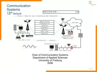
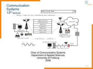
Communication SystemsISDN – and the OSI protocol stack (mostly D channel) 29 | 54
Communication SystemsISDN – Basic Rate Interface • BRI provides a total data rate of 160kbit/s • standard end user connection • 2 B channels (“bearer” - for data, digitized voice, ...) of 64kbit/s each • 1 D channel (data channel for out-of-band signaling) of 16kbit/s • synchronization of 16kbit/s 30 | 54
Communication SystemsISDN – Basic Rate Interface • Physical layer specifications of the Uk0 • operates over two-wire cable up to 5 km (depending on cable diameter and quality) • switching center provides a 90V current to power the NTBA and one device (emergency function – to be independent on local power supply for at least one telephone) • other physical layer specifications for alternate U interfaces 31 | 54
Communication SystemsISDN – Basic Rate Interface • BRI network termination is defined by the Uk0 interface • a special encoding (4B3T) is used: 4 bit digital to 3 baud ternary • 4B3T is a "block code" that uses Return-to-Zero states • allows reduction of symbol rate to 120 kBaud (¾th) and thus distances up to 8km • reduction of low frequencies in the signal spectrum • better detection of code errors • three states: negative pulse, no pulse, positive pulse 32 | 54
Communication SystemsISDN – Basic Rate Interface • Next state (S1 - S4) to be transmitted is indicated in column labeled Go 33 | 54
Communication SystemsISDN – Basic Rate Interface • Alternate encoding: 2B1Q – 2 bit digital to 1 baud quaternary representation • 2B1Q transmission can be simply described as an amplitude modulation scheme for DC pulses • Ordering of data blocks depends on the encoding used 34 | 54
Communication SystemsUk0 – bit streams from switching center to NTBA • Each frame consists of 120 ternary steps • 2*B+1*D takes 108 steps in 4 ternary blocks (tb) with 27 steps each • sync channel occupies 11 steps and a “maintenance” channel (mc) 1 step 35 | 54
Communication SystemsUk0 – bit streams from NTBA to switching center • Connection is full-duplex over the two wires • echo compensation and terminating set is needed • NTBA splits the data streams to separate up and down onto the S0 bus 36 | 54
Communication SystemsISDN – Basic Rate Interface • Instead of the traditional wall socket a NTBA (network terminal base adapter) is needed at end users site • NTBA provides the S0 bus to which end user devices are connected • unidirectional – on pair of wires for each direction • allows up to 12 wall sockets, 8 ISDN devices (or analogous devices via a/b converter) • provides device power up to 4,5W 37 | 54
Communication SystemsISDN – S0 • Provides the same B and D channels as Uk0 • maintains the step and octet frequency • handles the device plugging and device activation, deactivation • has to be terminates with resistors of 110 Ohm • uses modified AMI code with currents of -0,75 and 0,75V 38 | 54
Communication SystemsS0 – AMI code • Modified AMI code (avoid long sequences of symbols of the same type) 39 | 54
Communication Systemsdata link layer for the D channel • No distinct layering for B channels – PCM or data directly put into frames as shown on previous slides • LAPD – Link Access Procedure on D channel • derived from High-Level Data Link Control Protokoll (HDLC) • broadcasts only for network termination device • D2 frame margin – octet of binary pattern: 01111110 • Keeping of frame sequence • Error discovery • Multiplexing of more than one logical D2 connections • Flow control 40 | 54
Communication Systemshigher layer protocols for the D channel • ITU Recommendation Q.921 41 | 54
Communication Systemslayer 2 for the D channel • Flag • character is part of the Header information, hexadecimal 7E • Address is two bytes (octets) long, and consists of three fields • Service Access Point Identifier (SAPI) • Command/Response (C/R) bit • Terminal Endpoint Identifier (TEI) 42 | 54
Communication Systemslayer 2 for the D channel • Control one or two octets (bytes) in length, indicates one of three frame formats • information • supervisory • unnumbered • Information carries Layer 3 Call Control (Q.931) data • it may carry Unnumbered Information data (TEI assignment) or XID (Connection Management/parameter negotiation) information 43 | 54
Communication Systemsdata link layer for the D channel • Protocol handles the TEI (Terminal Endpoint Identifier) allocation • all devices on S0 using the same bus and have to be addressable • TEI assignment is started by the connected devices after successful initialization of physical layer synchronization • non automatic assignment uses ID0 – 63, automatic 64 – 126 • there is a special group TEI 127 • Protocol elements • information lowermost bit is set to 0 44 | 54
Communication Systemsdata link layer for the D channel • Protocol elements • Receive Ready - (01) • Set Asyncronous Balance Mode Extended - (6F/7F) • Unnumbered Information - (03) • Disconnect - (43/53) • Unnumbered Acknowledgement – (63/73) • Flow control uses sequence numbers for sending and receiving 00:E1:04:00:... • Octets #4 for sending and #5 for receiving in the information frame 45 | 54
Communication Systemsdata link layer for the D channel error detection • D channel protocol uses rather sophisticated error detection protocol • Generates frame checksums • Generator polynom g(x) = (x +1)(x15+x14+x13+x12+x4+x2+x +1) g(x) = x16+x12+x5+1 • 16 bit frame checksum • Inverted residue of binary division p1(x) = xk (x15+x14+...+x2+x +1) p2(x) = x16d(x) 46 | 54
Communication Systemsdata link layer for the D channel error detection • Checking for added or lost binary zeros • Thus cyclic Hamming codes implemented • Error detection for one, two and three bit error 47 | 54
Communication Systemsnetwork layer for the D channel • DSS1 protocol handels the call setup of the calling and called site • Call destruction after finishing the session • Restaring and parking if required • Error handling 48 | 54
Communication SystemsDSS1 layer 3 protocol • Protocol Discriminator • part of the Layer 3 header information • single byte (octet) that is usually set to a value of 00001000 (hexadecimal "08") - meaning Q.931 call maintenance • Reference Value consists of either two or three bytes (octets) • BRI systems have a 7-bit Call Reference value (127 references) • no particular end-to-end significance • Either end can assign an arbitrary value • used to associate messages with a particulary channel connection 49 | 54
Communication SystemsDSS1 layer 3 protocol • Message Type single byte (octet) that indicates what type of message is being sent/received 50 | 54