Download

1 / 10
110 likes | 121 Views
All about Classification of Centrifugal Pumps

E N D
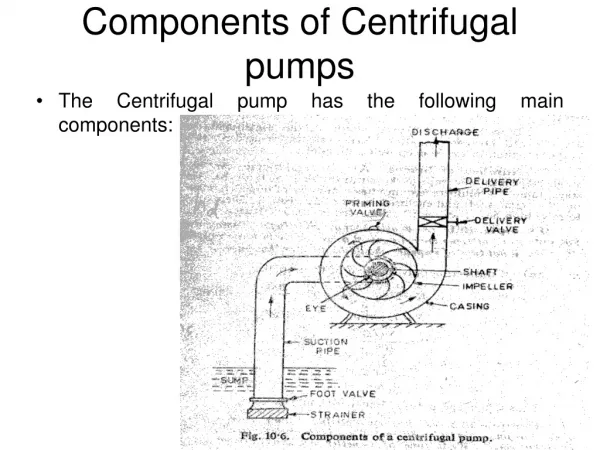
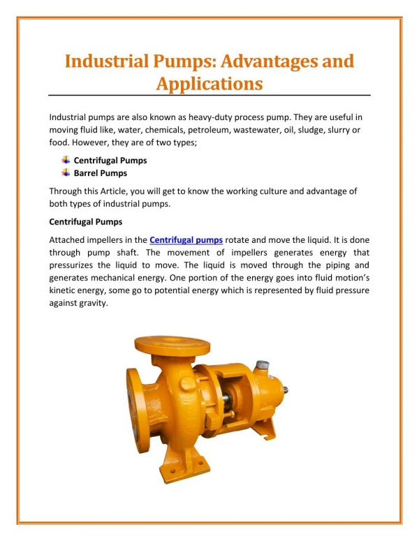
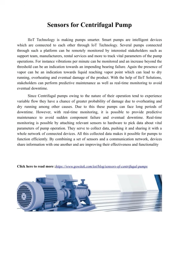
A centrifugal pump transports liquid by accelerating it radially outward in a revolving element (called an impeller) to a surrounding chamber. The impeller is a revolving disc with vanes attached to it. The rotational and flow directions are indicated by arrows. The impeller’s vanes are curled backward because this design gives the most consistent flow characteristics. Because of its simple construction and inexpensive cost, this type of pump is by far the most frequent in usage in buildings. The different types of centrifugal pumps used in buildings can be confusing because they are classified in a variety of ways, including
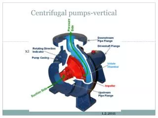
Internal Design A pump’s case is the enclosure that encloses the impeller and collects the pumped liquid. The liquid enters through the impeller’s eye, which is placed in the center. The impeller is responsible for transferring energy to the liquid. The liquid is ejected with a considerably enhanced velocity at the periphery after being turned by the vanes on the impeller. Through a spiral-shaped channel known as a volute, it is guided to the discharge nozzle. This form is intended to produce an even flow velocity along the circumference.
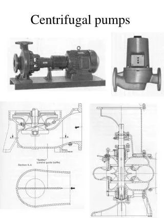
Single-Suction vs. Double-Suction Configuration, The most commonly used single-suction pump has a spiral-shaped housing. Only one side of the impeller receives water. Water enters both sides of the double-suction impeller in a double-suction pump, effectively eliminating hydraulic imbalance. Problems with the inlet design of high-flow pumps are somewhat alleviated because only half of the flow enters each side of the impeller. The impeller is normally supported by two bearings, and the casing is split axially to allow for easy pump maintenance.
The shape of the Impeller The shrouds, which are discs that encase the impeller vanes, are curved to minimize the shock losses of flow in the liquid as it goes from the eye to the shrouds. An open impeller does not have any shrouds. When the water being pumped contains suspended particulates, this type is typically used. An impeller with two shrouds is known as a closed impeller. It requires minimum maintenance and, in most cases, outlasts open impellers in terms of working efficiency. The impeller is called a partly open impeller if it just has one shroud.
Casing Design The casing is divided into two types: radially split and axially split. The axially split casing is split parallel to the shaft axis, allowing the pump to be accessed without disrupting the system pipework, making service easier. Casings that are radially split are split perpendicular to the shaft axis, resulting in a more straightforward joint design.
Position of the Pump Horizontal dry-pit support is one in which the pump is installed in a dry place with the shaft horizontal, such as a basement floor or even a specific pit built for the pump. The floor supports the pump assembly, and the structural baseplate is normally grouted to the floor. This is the most typical form of assistance. In-line pumps are supported directly by the system piping, which means that the piping bears the pump’s weight. To minimize floor space and center the weight over the pipes, the pump-motor assembly is commonly positioned vertically. Some smaller pumps may be suspended from the pipes horizontally, such as horizontal centrifugal pump, whereas bigger vertically installed pumps may rest on the floor. Pumps that are submerged in the liquid to be pumped are known as wet-pit pumps. This is most frequent with sump pumps, which have the pumping end immersed in the sump’s liquid. The pump might be suspended from a structural floor above the sump or supported on the sump’s floor.
Stages of the Pump There is only one impeller in a single-stage pump. The pump generates the complete head in a single stage. A pump with two or more impellers is known as a multistage pump. Multiple stages are involved in the development of the entire head. Vertical turbine pumps are a sort of multistage pump that is unlike any other. They’re long and slim, and they’re built to pump water from deep wells.
Connection between motor and pump A separately coupled pump has an electric motor drive that is connected to the pump through a flexible coupling. To provide support and preserve shaft alignment, both the pump and the motor are installed on a solid base plate. A close-coupled pump is one in which the motor and pump share the same shaft. This design has a minimal initial cost and installation cost, and it eliminates the alignment problem. Engine noise may be conveyed to the pump and pipework. A motor-face-mounted pump is one in which the pump and the motor are connected independently.
This setup eliminates the need for a structural connection between the pump and the motor. It does away with the necessity for a structural baseplate and reduces the likelihood of coupling alignment issues. Price pump provides you with the best suitable pump for your needs. For quality magnetic drive pumpvisit price Pump. Source: https://digestley.com/all-about-classification-of-centrifugal-pumps/