Download
1 / 21
770 likes | 2.65k Views
Components of Centrifugal pumps. The Centrifugal pump has the following main components:. Components of centrifugal pumps. Impeller

E N D
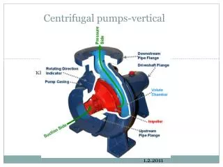
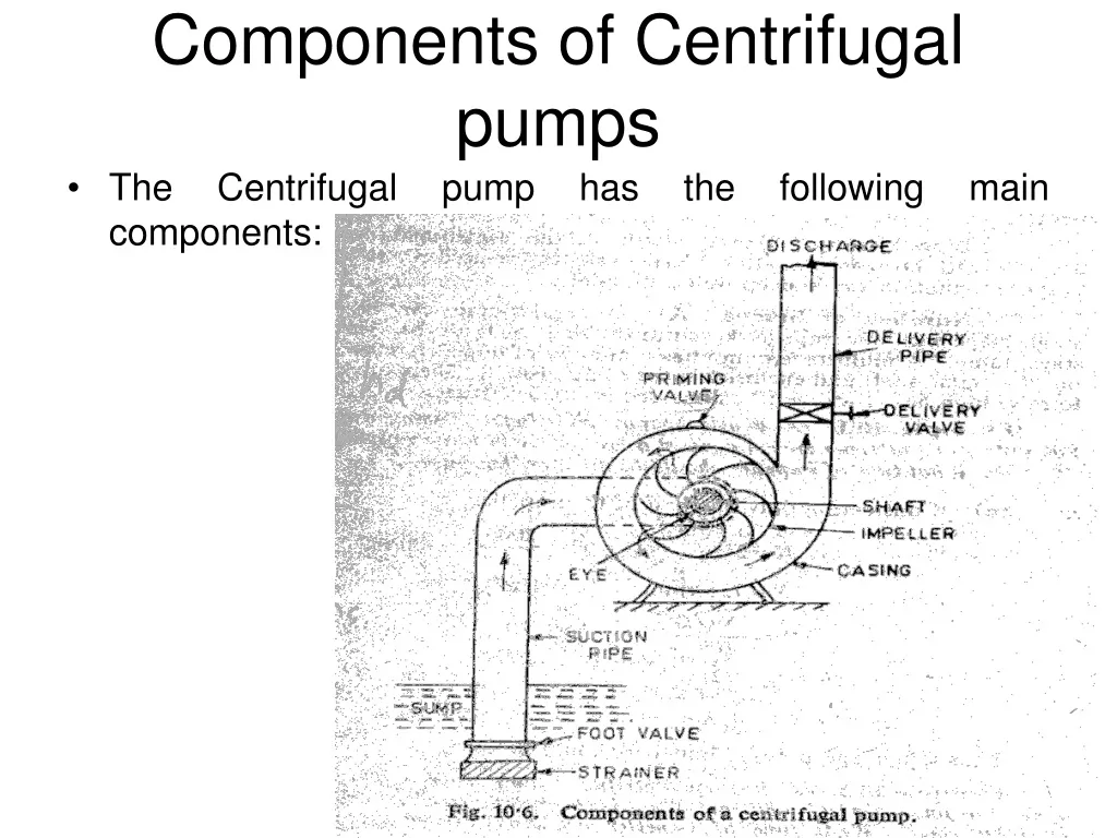
Components of Centrifugal pumps • The Centrifugal pump has the following main components:
Components of centrifugal pumps • Impeller A rotating wheel fitted with a series of backward curved vanes or blades mounted on a shaft connected to the shaft of an electric motor. Due to rotation of impeller centrifugal force is produced on the liquid, which produces kinetic energy in the liquid. Water enters at the centre of the impeller and moves radially outward and then leaves from outer periphery of the impeller with a very high kinetic energy.
Components of centrifugal pumps • Casing It is an airtight chamber, which accommodates the rotating impeller. The area of flow of the casing gradually increases in the direction of flow of water to convert kinematic energy into pressure energy.
Components of centrifugal pumps • Suction pipe It is the pipe through which water is lifted from the sump to the pump level. Thus the pipe has its lower end dipped in the sump water and the upper end is connected to the eye or the inlet of the pump. At the lower end, a strainer and a foot-valve are also fitted. i. Strainer It is a screen provided at the foot of the suction pipe, it would not allow entrance of the solid matters into the suction pipe which otherwise may damage the pump.
Components of centrifugal pumps • Suction pipe ii. Foot valve It is a one direction valve provided at the foot of the suction pipe. It permits flow only in one direction i.e. towards the pump. Foot valve facilitates to hold the primed water in the suction pipe and casing before starting the pump. Priming is the process of filling of water in centrifugal pump from foot valve to delivery valve including casing before starting the pump.
Components of centrifugal pumps • Delivery pipe Delivery pipe is used for delivery of liquid. One end connected to the outlet of the pump while the other delivers the water at the required height to the delivery tank. It consists of following components: i. Delivery gauge This gauge connected on the delivery side of the pump to measure the pressure on the delivery side. ii. Delivery Valve It is a gate valve on the delivery side of the pump to control the discharge
Components of centrifugal pumps • Shaft It is a rotating rod supported by the bearings. It transmits mechanical energy from the motor to the impeller. • Air Relieve Valve These are the valves used to remove air from casing while priming.
Working of centrifugal pump • Works on the principle that when a certain mass of fluid is rotated by an external source, it is thrown away from the central axis of rotation and a centrifugal head is impressed which enables it to rise to a higher level. • In order to start a pump, it has to be filled with water so that the centrifugal head developed is sufficient to lift the water from the sump. The process is called priming. • Pump is started by electric motor to rotate the impeller. • Rotation of impeller in casing full of water produces forced vortex which creates a centrifugal head on the liquid.
Working of centrifugal pump • The delivery valve is opened as the centrifugal head is impressed. • This results in the flow of liquid in an outward radial direction with high velocity and pressure enabling the liquid to enter the delivery pipe. • Partial vacuum is created at the centre of the impeller which makes the sump water at atmospheric pressure to rush through the pipe. • Delivery of water from sump to delivery pipe continues so long as the pump is on.
Heads of a Pump • Static Head It is the vertical distance between water levels in the sump and the reservoir. Let Hst = Static head on the pump hs = Height of the centre line of pump above the sump level (Suction head) hd = Height of the liquid level in the tank above the centre line of pump (Delivery head) Then, Hst = hs + hd
Heads of a Pump • Total Head It is the total head which has to be developed by a pump to deliver the water form the sump into the tank. Apart from producing the static head, a pump has also to overcome the losses in pipes and fittings and loss due to kinetic energy at the delivery outlet. Let H = Total head hfs = Losses in suction pip hfd = Losses in delivery pipe hf = Total friction loss in pipe = hfs + hfd Vd = Velocity of liquid in delivery pipe. Then H = hs+ hd + hfs + hfd + Vd2/(2g) Losses in the casing and the impeller are not taken into account in the total head.
Heads of a Pump • Manometric Head It is usually not possible to measure exactly the losses in the pump casing. So, a term known as manometric head is introduced. It is the rise in pressure energy of the liquid in the impeller of the pump. If two pressure gauges are installed on the suction and the delivery sides as near to the pump as possible, the difference in their reading will give the change in the pressure energy in the pump or the manometric head. Hm = Manometric head of the pump Hms = Reading of the pressure gauge on the suction side Hmd = Reading of the pressure gauge on the delivery side. Then Hm = Hmd - Hms
Losses and Efficiencies • Hydraulic Efficiency Hydraulic losses are the losses the occur between the suction and the delivery ends of a pump. Hydraulic efficiency varies from 0.6 to 0.9. • Manometric Efficiency Manometric efficiency is defined as the hydraulic efficiency of an ideal pump.
Losses and Efficiencies • Volumetric Efficiency The pressure at the outlet of the impeller is higher than at the inlet. Thus there is always a tendency on the part of water to slip back or leak back through the clearance between the impeller and the casing. There can also be some leakage from the seals. These are called volumetric losses. Volumetric efficiency is the ratio of the actual discharge to the total discharge. Q = Amount of discharge Let ∆Q = Amount of leakage. ηv = Q / (Q+ ∆Q) Its value lies between 0.97 and 0.98.
Losses and Efficiencies • Mechanical Efficiency Mechanical losses in case of a pump are due to (a) Friction in bearings (b) Disc friction as the impeller rotates in liquid. Mechanical efficiency is the ratio of the actual power input to the impeller and the power given to the shaft. Let P = Total power input to the shaft ∆ P = Mechanical losses ηm = (P - ∆ P) / P Its value lies between 95% - 98%.
Losses and Efficiencies • Overall Efficiency It is the ratio of the total head developed by a pump to the total power input to the shaft. ηo = (ρQgH) / P Range of overall efficiency is between 0.71 to 0.86.
Problem: A centrifugal pumps delivers 50 liters of water per second to a height of 15m through a 20 m long pipe. Diameter of the pipe is 14 cm. Overall efficiency is 72 %, and the coefficient of friction 0.015. Determine the power needed to drive the pump. Solution: Hs = 15m Q=0.05 m3/s I = 20 m f = 0.015 d = 0.14 m ηo = 72% We have, ηo = (ρQgH) / P H = Hs+ Hf + Vd2/(2g)
Problem: Solution: For which Vd is given by, Q = π/4 d2 Vd 0.05=π/4(0.14)2 Vd Vd = 3.25 m/s And hf = (4flVd2) / (2gd) hf = (4x0.015x20x3.252)/(2x9.81x0.14) hf = 4.61 m H=15+4.61+ 3.252/(2x9.81)= 20.15m Power to drive pump can be calculated as follows: ηo = (ρQgH) / P 0.72 = (1000x0.05x9.81x20.15) / P Or P = 13726 W = 13.726 k W.
Multistage Pumps To develop a high head, the tangential speed μo has to be increased. However an increase in the speed also increases the stresses in the impeller material. This implies that centrifugal pump with one impeller cannot be used to raise high heads. More than one pump is needed to develop a high head. The discharge of one pump is delivered to the next to further augment the head. However, a better way is to mount two or more impellers on the same shaft and enclose them in the same cashing. All the impellers are put in series so that the water coming out of one impeller is directed to the next impeller and so on (Fig.10.22).