Download
1 / 46
460 likes | 475 Views
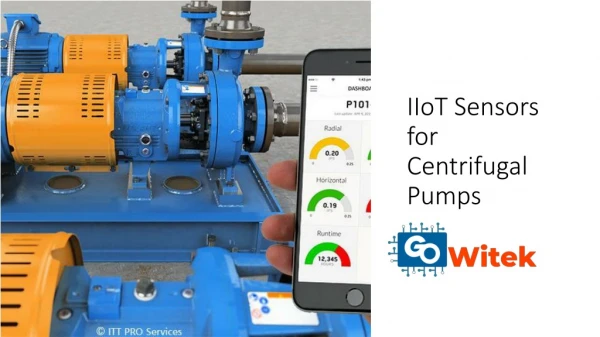
As a Manufacturer of Hygienic Centrifugal Pump, Alfa Laval LKH Multistage is designed to meet the hygienic requirements of the dairy, food, beverage and personal care industries.

E N D
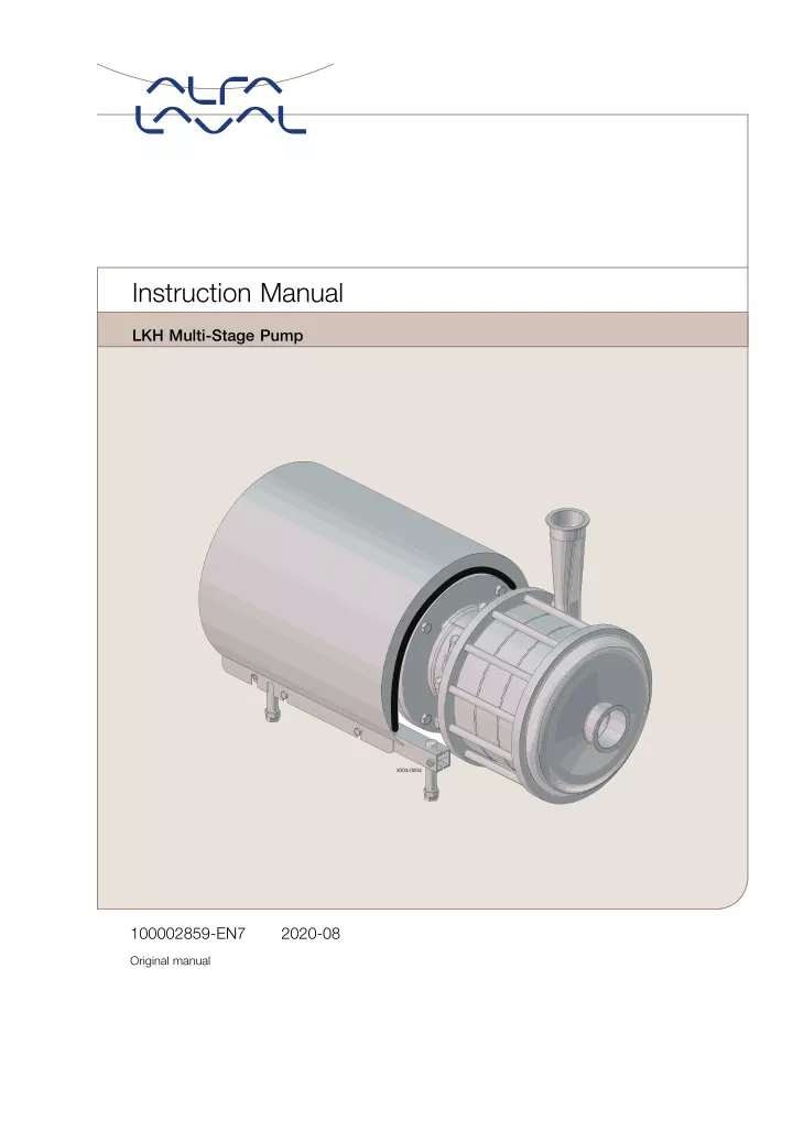
Instruction Manual LKH Multi-Stage Pump 3003-0004 100002859-EN7 2020-08 Original manual
Table of contents The information herein is correct at the time of issue but may be subject to change without prior notice 1. EC Declaration of Conformity ....................................................................... 4 2. Safety .................................................................................................... 2.1. Important information ............................................................................. 2.2. Warning signs ..................................................................................... 2.3. Safety precautions ................................................................................ 5 5 5 6 3. Installation .............................................................................................. 3.1. Unpacking/delivery ............................................................................... 3.2. Installation/Pre-use Check ....................................................................... 3.3. Recycling information ............................................................................. 7 7 8 10 4. Operation 4.1. Operation/Control ................................................................................. 4.2. Trouble shooting .................................................................................. 4.3. Recommended cleaning ......................................................................... ............................................................................................... 11 11 13 14 5. Maintenance 5.1. General maintenance ............................................................................. 5.2. Cleaning Procedure ............................................................................... 5.3. Dismantling of pump/shaft seals ................................................................ 5.4. Assembly of Pump/Assembly of Shaft Seal - LKH-110 ....................................... 5.5. Assembly of Pump/Assembly of Shaft Seal - LKH-120/P ........................................................................................... 15 15 16 17 21 27 .................................... 6. Technical data 6.1. Technical data 6.2. Relubrication intervals 6.3. Torque Specifications ............................................................................. 6.4. Weight (kg) ........................................................................................ 6.5. Noise emission .................................................................................... ......................................................................................... ..................................................................................... ............................................................................ 32 32 33 34 35 36 7. Parts list and service kits 7.2. LKH Multi-Stage - Wet end 7.3. LKH Multi-Stage - Motor dependent parts 7.4. LKH Multi-Stage - Shaft seal and Service kits ............................................................................ ...................................................................... ..................................................... ................................................. 37 38 40 42 3
1 EC Declaration of Conformity Revision of Declaration of Conformity 2009-12-29 The Designated Company Alfa Laval Kolding A/S Company Name Albuen 31, DK-6000 Kolding, Denmark Address +45 79 32 22 00 Phone No. hereby declare that Pump Designation LKH-112, LKH-112/P, LKH-113, LKH-113/P, LKH-114, LKH-114/P, LKH-122/P, LKH-123/P, LKH-124/P Type From serial number 10.000 to 1.000.000 is in conformity with the following directive with amendments: - Machinery Directive 2006/42/EC The person authorised to compile the technical file is the signer of this document Global Product Quality Manager Pump, Valves, Fittings and Tank Equipment Title Lars Kruse Andersen Name Kolding Place 2013-12-03 Date Signature 4
2 Safety Unsafe practices and other important information are emphasized in this manual. Warnings are emphasized by means of special signs. Always read the manual before using the pump! Always read the manual before using the pump! 2.1 Important information WARNING WARNING Indicates that special procedures must be followed to avoid serious personal injury. CAUTION CAUTION Indicates that special procedures must be followed to avoid damage to the pump. NOTE NOTE Indicates important information to simplify or clarify procedures. 2.2 Warning signs General warning: General warning: Dangerous electrical voltage: Dangerous electrical voltage: Caustic agents: Caustic agents: 5
2 Safety All warnings in the manual are summarized on this page. Pay special attention to the instructions below so that severe personal injury and/or damage to the pump are avoided. 2.3 Safety precautions Installation: Always Always read the technical data thoroughly. (See chapter 6 Technical data) ALways ALways use a lifting crane when handling the pump Always Always use a lifting crane when handling the pump. Never Never start in the wrong direction of rotation with liquid in the pump. Installation: ! Always Always have the pump electrically connected by authorized personnel. (See the motor instruction) Operation: Always Always read the technical data thoroughly. (See chapter 6 Technical data) Never Never touch the pump or the pipelines when pumping hot liquids or when sterilising. Never Never run the pump with both the suction side and the pressure side blocked. Never Never run the pump when partially installed or not completely assembled. Necessary Necessary precautions must be taken if leakage occurs as this can lead to hazardous situations. Operation: ! Always Always handle lye and acid with great care. Never Never use the pump for products not mentioned in Alfa Laval pump selection program. Alfa Laval pump selection program can be acquired from your local Alfa Laval sales company. Maintenance: Always Always read the technical data thoroughly. (See chapter 6 Technical data) Never Never service the pump when it is hot. Never Never service the pump if pressurized. Maintenance: ! Motors with grease nipples: Motors with grease nipples: Remember lubrication according to information plate/label on the motor. Always Always disconnect the power supply when servicing the pump. Always Always use Alfa Laval genuine spare parts. Transportation: Transportation of the pump or the pump unit: Never Never lift or elevate in any way other than described in this manual Always Always drain the pump head and accessories of any liquid Always Always ensure that no leakage of lubricants can occur Always Always transport the pump in it’s upright position Always Always ensure that the unit is securely fixed during transportation Always Always use original packaging or similar during transportation Transportation: Transportation of the pump or the pump unit: 6
3 Installation The LKH-110 and -120P pump is highly efficient and econominal centrifugal pump, which meets the requirements of sanitary and gently product treatment and chemical resistance. LKH-110 and the LKH-120P is avaliable in the following sizes, LKH-112, -113, -114 and LKH122/P, -123/P, -124/P. The instruction manual is part of the delivery. Study the instructions carefully. The large pump sizes are very heavy. ALfa Laval recommends the use of a lifting crane when handling the pump. 3.1 Unpacking/delivery Step 1 Step 1 Check the delivery for: Check the delivery for: 1. Complete pump. 2. Delivery note. 3. Instruction manual. 4. Motor instructions. 5. Test certificate, IF ORDERED! Always Always use a lifting crane when handling the pump CAUTION CAUTION Alfa Laval cannot be held responsible for incorrect unpacking. WARNING: WARNING: Be aware that certain pump configurations can tilt, and thereby cause injuries to feet or fingers. The pump should be supported underneath the adaptor, when not installed in the process line. Step 2 Step 2 Remove possible packing materials from the inlet and the outlet. Avoid damaging the inlet and the outlet. Avoid damaging the connections for flushing liquid, if supplied. Remove packing materials! 3003-0005 Step 3 Step 3 Inspect the pump for visible transport damages. Inspection! 3003-0006 Step 4 Step 4 Always remove the shroud, if fitted, before lifting the pump. Remove the shroud before lifting! 3003-0007 7
3 Installation Study the instructions carefully and pay special attention to the warnings! The direction of rotation of the impeller can be checked by observing the direction of rotation of the motor fan. - See the indication label on the pump. 3.2 Installation/Pre-use Check Step 1 Step 1 Always Always read the technical data thoroughly. (See technical data on page 32) Never Never start in the wrong direction of rotation with liquid in the pump. (See Pre-use check on page 9) Always Always have the pump electrically connected by authorised personnel. (See the motor instructions). CAUTION CAUTION Alfa Laval cannot be held responsible for incorrect installation. WARNING: WARNING: Alfa Laval recommend the installation of lockable repair breaker. If the repair breaker is to be used as an emergency stop the colors of the repair breaker must be red and yellow. Caution: Caution: The pump does not prevent back flow when intentionally or unintentionally stopped. If back flow can cause any hazardous situations precautions must be taken e.g. check valve to be installed in the system preventing above described. Step 2 Step 2 Ensure at least 0.5 m (1.6 ft) clearance around the pump. 3003-0008 Step 3 Step 3 Check that the flow direction is correct. O: Outlet I: Inlet Correct! O ? I 3003-0009 8
3 Installation Study the instructions carefully and pay special attention to the warnings! The direction of rotation of the impeller can be checked by observing the direction of rotation of the motor fan. - See the indication label on the pump. Step 4 Step 4 1. Ensure that the pipelines are routed correctly. 2. Ensure that the connections are tight. Remember seal rings! 3003-0010 Correct! Few bends Step 5 Step 5 Avoid stressing the pump. Pay special attention to: - Vibrations. - Thermal expansion of the tubes. - Excessive welding. - Overloading of the pipelines. Risk of damage! ! 3003-0011 Step 6 Pre-use check: Pre-use check: 1. Start and stop the motor momentarily. 2. Ensure that the direction of rotation of the motor fan is clockwise as viewed from the back of the motor. Step 6 Correct rotation direction! See the indication label! Rear view of motor ? 3003-0012 Note Note In case of shaft seal leakage the media will drip from the slot in the bottom of the adaptor. In case of shaft seal leakage Alfa Laval recommend to put a drip tray underneath the slot for collecting the leakage. 9
3 Installation 3.3 Recycling information • Unpacking • Unpacking - - - - Packing material consists of wood, plastics, cardboard boxes and in some cases metal straps. Wood and cardboard boxes can be reused, recycled or used for energy recovery. Plastics should be recycled or burnt at a licensed waste incineration plant. Metal straps should be sent for material recycling. • Maintenance • Maintenance During maintenance oil and wear parts in the machine are replaced. All metal parts should be sent for material recycling. Worn out or defective electronic parts should be sent to a licensed handler for material recycling. Oil and all non metal wear parts must be taken care of in agreement with local regulations. - - - - • Scrapping • Scrapping - At end of use, the equipment shall be recycled according to relevant, local regulations. Beside the equipment itself, any hazardous residues from the process liquid must be considered and dealt with in a proper manner. When in doubt, or in the absence of local regulations, please contact the local Alfa Laval sales company. 10
4 Operation Study the instructions carefully and pay special attention to the warnings! 4.1 Operation/Control Step 1 Step 1 Always Always read the technical data thoroughly. See technical data on page 32 CAUTION CAUTION Alfa Laval cannot be held responsible for incorrect operation/control. Never Never touch the pump or the pipelines when pumping hot liquids or when sterilising. Step 2 Step 2 Danger of burns! Danger of burns! Never Never touch the pump or the pipelines when pumping hot liquids or when sterilising. 3003-0013 Step 3 Step 3 Danger of explosion! Danger of explosion! ! Never Never run the pump with both the suction side and the pressure side blocked. See warning label on pump. ! 3003-0014 11
4 Operation Study the instructions carefully and pay special attention to the warnings! Step 4 Step 4 ? CAUTION CAUTION The shaft seal must not run dry. Do not allow to run dry run dry Do not allow to CAUTION Never Never throttle the inlet side. CAUTION ? 3003-0015 Step 5 Flushed shaft seal: Flushed shaft seal: 1. Connect the inlet of the flushing liquid correctly. 2. Regulate the water supply correctly. 3. Observe the steam data. Step 5 Correct! ? O Tmax = 100°C Pmax = 1 bar (flush seal) O: Outlet I: Inlet 3003-0016 I Step 6 Control: Control: Reduce the capacity and the power consumption by means of: Step 6 Throttling! - - - Throttling the pressure side of the pump. Reducing the impeller diameter. Reducing the speed of the motor. 3003-0017 12
4 Operation Pay attention to possible faults. Study the instructions carefully. 4.2 Trouble shooting NOTE! NOTE! Study the maintenance instructions carefully before replacing worn parts. - See section 5.1 General maintenance on page 15 Remedy Remedy Problem Problem Cause/result Cause/result - - - - Pumping of viscous liquids Pumping of liquids with high density Low outlet pressure (counter pressure) - Lamination of precipitates from the liquid - Larger motor or smaller impeller Overloaded motor Higher counter pressure (throttling) Frequent cleaning - - - Damage Pressure reduction (sometimes to zero) Increasing of the noise level - - Low inlet pressure High liquid temperature - - Increase the inlet pressure Reduce the liquid temperature - - Reduce the pressure drop before the pump Leaking shaft seal - Dry run Replace: All wearing parts - Incorrect rubber grade If necessary: - Change rubber grade - Abrasive particles in the liquid - Select stationary and rotating seal ring in Silicon Carbide/Silicon Carbide Incorrect rubber grade Leaking O-ring seals Change rubber grade 13
4 Operation The pump is designed for cleaning in place (CIP). CIP = Cleaning In Place. Study the instructions carefully and pay special attention to the warnings! NaOH = Caustic Soda. HNO3 = Nitric acid. 4.3 Recommended cleaning Step 1 Step 1 Caustic danger! Caustic danger! Always Always handle lye and acid with great care. Always use rubber gloves! Always use protective goggles! Step 2 Step 2 Danger of burns! Danger of burns! Never Never touch the pump or the pipelines when sterilizing. 3003-0013 Step 3 Step 3 Examples of cleaning agents: Examples of cleaning agents: Use clean water, free from chlorides. 1. 1% by weight NaOH at 70°C (158°F). + 1. Avoid excessive concentration of the cleaning agent ⇒ Dose gradually! 2. Adjust the cleaning flow to the process. Sterilization of milk/viscous liquids ⇒ Increase the cleaning flow! 1 kg (2.2 lb) NaOH 100 l (26.4 gal) water = Cleaning agent. + 2.2 l (0.6 gal) 33% NaOH 100 l (26.4 gal) water = Cleaning agent. 2. 0.5% by weight HNO3at 70°C (158°F). + 0.7 l (0.2 gal) 53% HNO3 100 l (26.4 gal) water = Cleaning agent. Step 4 Step 4 Always rinse! Always rinse! Always Always rinse well with clean water after using a cleaning agent. NOTE NOTE The cleaning agents must be stored/disposed of in accordance with current regulations/directives. 3013-0153 Water Cleaning agent 14
5 Maintenance Maintain the pump carefully. Study the instructions carefully and pay special attention to the warnings! Always keep spare shaft seals and rubber seals in stock. See separate motor instructions. 5.1 General maintenance Step 1 Step 1 Always Always read the technical data thoroughly. (See technical data on page 32) Always Always disconnect the power supply when servicing the pump. NOTE NOTE All scrap must be stored/discharged in accordance with current rules/directives. Step 2 Step 2 Atmospherie pressure required! Danger of burns! Danger of burns! Never Never service the pump when it is hot. Never Never service the pump with pump and pipelines under pressure. 3003-0013 Step 3 Recommended spare parts: Recommended spare parts: Order Service Kits from Service kits list (see page 7 Parts list and service kits). Step 3 Ordering spare parts Ordering spare parts Contact your local Alfa Laval sales company. 15
5 Maintenance Maintain the pump carefully. Study the instructions carefully and pay special attention to the warnings! Always keep spare shaft seals and rubber seals in stock. See separate motor instructions. Rubber seals Rubber seals Motor bearings Motor bearings Shaft seal Shaft seal Preventive maintenance Replace after 12 months: Replace after 12 months: (one-shift) - Stationary and rotating seal ring - Quad-/O-rings Replace when replacing the shaft seal Maintenance after leakage (leakage normally starts slowly) Replace at the end of the day: day: - Stationary and rotating seal ring - Quad-/O-rings Replace at the end of the Replace when replacing the shaft seal Planned maintenance - Regular inspection for leakage and smooth operation Keep a record of the pump Use the statistics for planning of inspections Replace when replacing the shaft seal Yearly inspection is recommended - Replace complete bearing if worn - Ensure that the bearing is axially locked (See motor instructions) - - Replace after leakage: Replace after leakage: - Stationary and rotating seal ring - Quad-/O-rings Lubrication Before fitting Before fitting Lubricate the O-rings with silicone grease or silicone oil Before fitting Before fitting Silicone grease or silicone oil See “Relubrication Intervals”, section 6.2 Relubrication intervals on page 33 5.2 Cleaning Procedure Cleaning Procedure for Soiled Impeller Screw Tapped Hole: Cleaning Procedure for Soiled Impeller Screw Tapped Hole: 1. Remove stub shaft (7) per section 4 of Service manual. 2. Submerge and soak Stub Shaft for 5 minutes in COP tank with 2% caustic wash 3. Scrub the blind tapped impeller screw hole vigorously by plunging a clean 1/2” diameter sanitary bristle pipe brush in and out of the hole for two minutes while submerged. 4. Soak Stub Shaft (7) in acid sanitizer for 5 minutes, then scrub blind tapped hole as described in step 3 above. 5. Rinse well with clean water and blow-dry blind tapped hole with clean air. 6. Swab test the inside of the tapped hole to determine cleanliness. 7. Should the swab test fail, repeat steps 2 thru 6 above until swab test is passed. Should swab testing continue to fail, or time is of the essence, install a new (spare) Stub Shaft (7). 16
5 Maintenance Study the instructions carefully. The items refer to the parts list and service kits section. Handle scrap correctly. : Relates to the shaft seal. 5.3 Dismantling of pump/shaft seals Step 1 Step 1 Remove the cap nuts (29), washer (30), pump cover (49) and O-ring (32). 3003-0018_1 Step 2 Flushed shaft seal: Flushed shaft seal: Unscrew tubes (25) using a spanner.. Step 2 3003-0019 Step 3 Step 3 Remove screw (16) and adaptor guard (17). 3003-0020 17
5 Maintenance Study the instructions carefully. The items refer to the parts list and service kits section. Handle scrap correctly. : Relates to the shaft seal. Step 4 Step 4 Remove impeller screw (47) O-ring (41) and impeller (45). Counterhold with a screwdriver! 3003-0021 Step 5 Step 5 1. Remove intermediate casing (46) (3 or 4 stage) and/or pump casing (42). 2. Remove impeller (45) and O-rings (41) in between the stages. 3003-0022 Step 6 Step 6 Remove guide vanes (44) and O-ring (43) from intermediate casing (3 or 4 stage) and /or pump casing (42). 3003-0023 Step 7 Step 7 Remove impeller (40) and the rotating part of the shaft seal, and remove O-ring (41) from impeller. 3003-0024 18
5 Maintenance Study the instructions carefully. The items refer to the parts list and service kits section. Handle scrap correctly. : Relates to the shaft seal. Step 8 Step 8 Remove space ring (35) and the rotating part of the seal from the impeller. 3003-0063 Step 9 Step 9 Remove rotating seal ring (36) the quad rings/O-rings (37, 39) and the supporting (38a) from rotating seal housing (38). 39 38 38a 37 36 3003-0064 Step 10 Step 10 1. Remove the nuts (20), the washers (21) and back plate (31). 2. Remove O-ring (32) from the back plate. 3003-0027 Step 11 Step 11 1. Remove stationary seal ring (34). 2. Remove O-ring (33) from the stationary seal ring. 3003-0028 19
5 Maintenance Study the instructions carefully. The items refer to the parts list and service kits section. Handle scrap correctly. : Relates to the shaft seal. Step 12 Flushed shaft seal: Flushed shaft seal: 1. Remove the screws (24) and seal housing (26). 2. Remove lip seal (28) and O-ring (27) from the seal housing. 3. Remove seal ring (23) from stub shaft (11). 4. Remove O-ring (22) from the seal ring. Step 12 3003-0029 Step 13 Step 13 1. Remove scroud (2). 2. Remove nuts (7), washers (8), screws (19) and adaptor (18). 3003-0030 Step 14 Step 14 1. Loosen the screws (15). 2. Remove stub shaft (11) and the compression rings (9,13). 3003-0031 Step 15 Step 15 Remove the screws (15), washers (15a) and the compression rings (9,13). 3103-0032 20
5 Maintenance Study the instructions carefully. The items refer to the parts list and service kits section. Handle scrap correctly. : Relates to the shaft seal. 5.4 Assembly of Pump/Assembly of Shaft Seal - LKH-110 Step 1 Step 1 1. Fit the compression rings (9,13), washers (15a) and the screws (15) on stub shaft (11). 2. Fit the stub shaft on the motor shaft. 3. Check the clearance between the end of the stub shaft and the motor flange. 10-20 mm (0.394-0.787 inch) 3003-0033 Step 2 Step 2 1. Tighten the screws (15) evenly. 2. Ensure that stub shaft (11) can be moved on the motor shaft. 3003-0034 Step 3 Step 3 Fit adaptor (18), screws (19), washers (8) and nuts (7). 3003-0035 21
5 Maintenance Study the instructions carefully. The items refer to the parts list and service kits section. Handle scrap correctly. : Relates to the shaft seal. Step 4 Step 4 Fit back plate (31), washers (21) and nuts (20). 3003-0036 Step 5 Step 5 1. Assemble the rotating part of the shaft seal. 2. Fit the seal part and the space ring on impeller (40). 40 35 CAUTION! CAUTION! Ensure that the driver in the rotating seal housing enters the notch in the rotating seal ring. 39 38 38a 3003-0065 37 36 Step 6 Step 6 1. Fit impeller (40,45) on stub shaft (11). Fit and tighten impeller screw (47). 2. Ensure that the clearance between impeller (40) and back plate (31) is 1mm (0.0394 inch). 1 mm 3003-0038 22
5 Maintenance Study the instructions carefully. The items refer to the parts list and service kits section. Handle scrap correctly. : Relates to the shaft seal. Step 7 Step 7 1. Remove impeller screw (47) and remove impeller (40,45) and back plate (31). 2. Tighten the screws (15) evenly to 15Nm. (11 lbf-ft ) 15 Nm (11 lbf-ft ) 3003-0039 Step 8 Step 8 1. Fit O-ring (33) on stationary seal ring (34). 2. Press the stationary seal ring in back plate (31). 3003-0040 Step 9 Flushed shaft seal: Flushed shaft seal: 1. Fit lip seal (28) in seal housing (26). 2. Fit O-ring (27) in the seal housing. 3. Fit the housing on back plate (31) and tighten the screws (24). Step 9 3003-0041 Step 10 Step 10 1. Fit back plate (31), washers (21) and nuts (20). 2. Fit O-ring (41) in impeller. Fit impeller (40) with shaft seal parts and space ring on shaft (11). 3. Fit O-ring (32) on the back plate. 3003-0042 23
5 Maintenance Study the instructions carefully. The items refer to the parts list and service kits section. Handle scrap correctly. : Relates to the shaft seal. Step 11 Step 11 LKH-112: 1. Fit pump casing (42) on back plate (31). 2. Fit O-ring (43) on casing. Fit guide vanes (44). 3. Fit O-ring (32) on guide vanes (44). 4. Go to Step 14 3003-0071 Step 12 Step 12 LKH-113: 1. Fit O-ring (41) in impeller (45). Fit impeller (45) on shaft (11). 2. Fit intermediatecasing (46). 3. Fit O-ring (43) on intermediate casing (46). Fit guide vane (44). 4. Fit O-ring (32) on guide vanes (44). 5. Go to Step 14 3003-0072 Step 13 Step 13 LKH-114: 1. Fit O-ring (41) in impeller (45). Fit impeller (45) on shaft (11). 2. Fit intermediate casing (46). 3. Fit O-ring (43) on intermediate casing (46). Fit guide vane (44). 4. Fit O-ring (32) on guide vanes (44). 3003-0073 Step 14 Step 14 1. Fit impeller (45) and O-ring (41) . 2. Fit and tighten impeller screw (47). Counterhold with a screwdriver! 3003-0045 24
5 Maintenance Study the instructions carefully. The items refer to the parts list and service kits section. Handle scrap correctly. : Relates to the shaft seal. Step 15 Step 15 1. Fit O-ring (32) and pump cover (49). 2. Fit washers (30) and cap nuts (29). 3. Tighten four cap nuts in following order. First 12 o’clock then 3, 9 o’clock and finally 6 o’clock. The rest to follow in random order. Torque values from Technical data section 6.3 are to be used. 4. NOTE! Tighten impeller screw with a socket wrench through the inlet. the inlet. 5. NOTE! Rotate the pump shaft by hand and insure the impellers runs smoothly without touching. impellers runs smoothly without touching. NOTE! Tighten impeller screw with a socket wrench through NOTE! Rotate the pump shaft by hand and insure the 3003-0046_1 Step 16 Step 16 1. Fit shroud (2). 2. Fit safety guard (17) and screw (16). If pump is not supplied with flush connections the holes in the adaptor shall be covered by the guard. 3003-0047 25
5 Maintenance Study the instructions carefully. The items refer to the parts list and service kits section. Handle scrap correctly. : Relates to the shaft seal. Step 17 Flushed shaft seal: Flushed shaft seal: Fit the tubes (25) on seal housing (26). Step 17 3003-0069 26
5 Maintenance Study the instructions carefully. The items refer to the parts list and service kits section. Lubricate the rubber seals before fitting them. : Relates to the shaft seal. 5.5 Assembly of Pump/Assembly of Shaft Seal - LKH-120/P Step 1 Step 1 1. Fit the compression rings (9,13) and the screws (15) on stub shaft (11). 2. Fit the stub shaft on the motor shaft. 3. Check the clearance between the end of the stub shaft and the motor flange. 10-20 mm (0,394-0,787 inch) 3003-0033 Step 2 Step 2 1. Tighten the screws (15) evenly. 2. Ensure that stub shaft (11) can be moved on the motor shaft. 3003-0034 Step 3 Step 3 Fit adaptor (18), screws (19), washers (8) and nuts (7). 3003-0035 27
5 Maintenance Study the instructions carefully. The items refer to the parts list and service kits section. Lubricate the rubber seals before fitting them. : Relates to the shaft seal. Step 4 Step 4 1. Fit O-ring (37) on stationary seal ring (34). 2. Press the stationary seal ring in back plate (31). 3003-0040 Step 5 Flushed shaft seal: Flushed shaft seal: 1. Fit lip seal (28) in seal housing (26). 2. Fit O-ring (27) in the seal housing. 3. Fit the housing on back plate (31) and tighten the screws (24). 4. Fit seal ring (23) with O-ring (22) on stub shaft (11). Step 5 3003-0041 Step 6 Step 6 Fit back plate (31), washers (21) and nuts (20). 3003-0036 Step 7 Step 7 1. Assemble the rotating part of the shaft seal. 2. Fit the seal part and the space ring on impeller (40). 40 35 CAUTION! CAUTION! Ensure that the driver in the rotating seal housing enters the notch in the rotating seal ring. 39 38 38a 3003-0065 37 36 28
5 Maintenance Study the instructions carefully. The items refer to the parts list and service kits section. Lubricate the rubber seals before fitting them. : Relates to the shaft seal. Step 8 Step 8 1. Fit back plate (31), washers (21) and nuts (20). 2. Fit O-ring (41) in impeller. Fit impeller (40) with shaft seal parts and space ring on shaft (11). 3. Fit O-ring (32) on the back plate. 3003-0042 Step 9 Step 9 LKH-122/P: 1. Fit pump casing (42) on back plate (31). 2. Fit O-ring (43) on casing. Fit guide vanes (44). 3. Fit O-ring (32) on guide vanes (44). 4. Go to Step 12 3003-0066_1 Step 10 Step 10 LKH-123/P: 1. Fit O-ring (41) in impeller (45). Fit impeller (45) on shaft (11). 2. Fit intermedia casing (46). 3. Fit O-ring (43) on intermediate casing (46). Fit guide vane (44). 4. Fit O-ring (32) on guide vanes (44). 5. Go to Step 12 3003-0067 Step 11 Step 11 LKH-124/P: 1. Fit O-ring (41) in impeller (45). Fit impeller (45) on shaft (11). 2. Fit intermediate casing (46). 3. Fit O-ring (43) on intermediate casing (46). Fit guide vane (44). 4. Fit O-ring (32) on guide vanes (44). 3003-0068_1 29
5 Maintenance Study the instructions carefully. The items refer to the parts list and service kits section. Lubricate the rubber seals before fitting them. : Relates to the shaft seal. Step 12 Step 12 1. Fit impeller (45) and O-ring (41). 2. Fit and tighten impeller screw lightly (47). Counterhold with a screwdriver! 3003-0045 Step 13 Step 13 1. Fit O-ring (32) and pump cover (49). 2. Fit the washers (30) and the cap nuts (29). 3. Tighten four cap nuts in following order. First 12 o’clock then 3, 9 o’clock and finally 6 o’clock. The rest to follow in random order. Torque values from Technical data section 6.3 are to be used. 4. NOTE! Tighten impeller screw (47) with a socket wrench through the inlet. through the inlet. NOTE! Tighten impeller screw (47) with a socket wrench 3003-0046_1 Step 14 Step 14 1. Push the shaft completely forward until the impeller touches the cover and zero set the dial gauge. 2. Push back the shaft 0.6 mm (0.0236 inch). 3. Tighten the screws in the compression coupling with 18 Nm (13.3 lbf-ft ). 4. NOTE! Rotate the pump shaft by hand and insure the impellers runs smoothly without touching. impellers runs smoothly without touching. NOTE! Rotate the pump shaft by hand and insure the Note: Note: Special tool for dial gauge is optional (9612927801) 3003-0070 Torque 18 Nm (13.3 lbf-ft) 30
5 Maintenance Study the instructions carefully. The items refer to the parts list and service kits section. Lubricate the rubber seals before fitting them. : Relates to the shaft seal. Step 15 Step 15 1. Fit shroud (2). 2. Fit safety guard (17) and screw (16). 3003-0047 Step 16 Flushed shaft seal: Flushed shaft seal: Fit the tubes (25) on seal housing (26). If pump is not supplied with flush connections the holes in the adaptor shall be covered by the guard. Step 16 3003-0069 31
6 Technical data It is important to observe the technical data during installation, operation and maintenance. Inform possible personnel about the technical data. 6.1 Technical data The LKH-110 and -120P pump is highly efficient and econominal centrifugal pump, which meets the requirements of sanitary and gently product treatment and chemical resistsnce. LKH-110 and the LKH-120P is available in the following sizes, LKH-112, -113, -114 and LKH122/P, -123/P, -124/P. The instruction manual is part of the delivery. Study the instructions carefully. The large pump sizes are very heavy. Alfa Laval therefore recommends the use of a lifting crane when handling the pump. Data Data Max. Max. inlet pressure: inlet pressure: Speed Speed Max 50Hz Max 50Hz Max 60Hz Max 60Hz Backplate Backplate Motor Motor Shat seal material Shat seal material Pump size Pump size LKH-112 LKH-113 LKH-114 LKH-112/P LKH-113/P LKH-114/P LKH-122/P LKH-123/P LKH-124/P C/SiC C/SiC 10 10 10 N/A N /A N/A 10 10 N/A Sic/SiC Sic/SiC 10 10 10 30 30 25 30 30 25 C/SiC C/SiC 10 10 10 N/A N/A N/A N/A N/A N/A SiC/SiC SiC/SiC 10 10 10 30 30 25 30 30 20 Std Std Std Special Special Special Special Special Special Std Std Std Reinforced Reinforced Reinforced Std Std Std Data Data Temperature range Noise level Max. speed Materials Materials Product wetted steel parts Other steel parts Product wetted seals Other O-rings Alternative seals Finish Shaft seal Shaft seal Seal types Max. temperature flush media Max. water pressure (flushed seal) Water consumption (flushed seal) Material, stationary seal ring Material, rotating seal ring -10°C to +140°C 60-80 dB(A) 3600 rpm (EPDM) (14°F to 284°F ) AISI 316L and Duplex steel Stainless steel EPDM (standard) EPDM Nitrile (NBR), Fluorinated rubber (FPM) Standard Blasted Single internal or flushed seal 70°C Normal atmosphere 0.25 - 0.5 l/min. Silicon carbide Carbon or silicon carbide (max. 1bar) (0.07-0.13 gal/min ) (14.5 psi ) Material, Quad-/O-rings Motor Motor EPDM (standard) Foot-flanged motor acc. to IEC metric standard 2 poles = 3000/3600 rpm. at 50/60 Hz IP55 (drain hole with labyrinth plug), insulation class F Motor types: - Standard motor with a fixed ball bearing on drive side - Special motor with fixed special bearings NOTE NOTE: Special motor must be ordered if required. 32
6 Technical data Relubrication interval 50 Hz (3000 rpm)/Relubrication interval 60 Hz (3600 rpm) Relubrication interval 50 Hz (3000 rpm)/Relubrication interval 60 Hz (3600 rpm). (Vendor) quantity in Drive End/quantity in Non Drive End. 6.2 Relubrication intervals The table is for 100°C internal bearing temperature.an increase in temperature of 15°C (ambient or internal in bearings), will reduce the greasing interval and bearing lifetime by 50%. Lubrication interval for vertically mounted pumps is half the value stated in the table. ABB IEC motors ABB IEC motors Frame Motor LKH-5 - 90 LKHPF-10 - 60 Frame Motor LKH-5 - 90 LKHPF-10 - 60 size power LKHI-10 - 60* LKHI-10 - 60 size power LKHI-10 - 60* LKHI-10 - 60 (kW) LKH-110* LKH-110 (kW) LKH-110* LKH-110 LKHSP 50/60 Hz LKHSP 50/60 Hz LKH Ultra Pure LKH Ultra Pure LKHex LKHex 50/60 Hz 50/60 Hz 80 0.75 Permanently lubricated 80 1.1 Permanently lubricated 90 1.5 Permanently lubricated Permanently lubricated 90 2.2 Permanently lubricated Permanently lubricated 100 3.0 Permanently lubricated 112 4.0 Permanently lubricated 4300h/3300h - DE/NDE:10g 132 5.5 Permanently lubricated 3600h/3000h - DE/NDE:15g 132 7.5 Permanently lubricated 3600h/3000h - DE/NDE:15g 160 11 Permanently lubricated 3100h/2300h - DE/NDE:25g 160 15 Permanently lubricated 3100h/2300h - DE/NDE:25g 160 18.5 Permanently lubricated 3100h/2300h - DE/NDE:25g 180 22 Permanently lubricated 2600h/2000h - DE/NDE:30g 200 30 Permanently lubricated 200 37 Permanently lubricated 200 45 Permanently lubricated 250 55 Permanently lubricated 250 75 Permanently lubricated * inlet pressure < 10 bar (145 psi ) LKH-85 LKH-85 50/60 Hz 50/60 Hz LKH-122/P LKH-122/P LKH-123/P LKH-123/P LKH-124/P LKH-124/P LKHPF-70 LKHPF-70 50/60 Hz 50/60 Hz 8000h/6000h - DE/NDE:42g 8000h/6000h - DE/NDE:40g 4500h/2000h - DE/NDE:55g 8000h/6000h - DE/NDE:40g 5000h/2500h - DE/NDE:55g 8000h/6000h - DE/NDE:40g 2500h/1000h - DE/NDE:55g 8000h/3000h - DE/NDE:60g 2500h/1000h - DE/NDE:73g 4000h/1500h - DE/NDE:60g 1500h/500h - DE/NDE:73g Recommended grease types: Recommended grease types: LKHPF-10/-70 – LKH-110 - LKH-120: LKHPF-10/-70 – LKH-110 - LKH-120: - Esso: Unirex N2 or N3 (Lithium complex base) - Shell: Albida EMS 2 (Lithium complex base) - FAG: Arcanol TEMP110 (Lithium complex base) - Mobil: Mobilith SHC 100 (Lithium complex base) - Klüber: Klüberplex BEM 41-132 (Special Lithium base) - Lubcon: Turmogrease L 802 EP PLUS (Lithium complex base) - Lubcon: Turmogrease PU703 (polyurea base) LKH-85: LKH-85: - Klüber: Klüberplex Quiet BQH 72-102 (polyurea base) WARNING: Polyurea based grease must not be mixed with Lithium complex base grease and vice versa. WARNING: Polyurea based grease must not be mixed with Lithium complex base grease and vice versa. 33
6 Technical data Relubrication interval 50 Hz (3000 rpm)/Relubrication interval 60 Hz (3600 rpm) Relubrication interval 50 Hz (3000 rpm)/Relubrication interval 60 Hz (3600 rpm). (Vendor) quantity in Drive End/quantity in Non Drive End. Table 1. Sterling Nema motors Table 1. Sterling Nema motors Type of service Type of service Standard Standard 8 hrs/day 8 hrs/day Motor RPM Motor RPM Frame Frame VS. HP VS. HP Heavy duty Heavy duty 24 hrs/day 24 hrs/day 143T - 286TS 1.5 - 30 324TS - 455TS 40 - 150 143T - 256T 1 - 20 284T - 326T 25 - 50 364T - 445T 60 - 150 143T - 256T 0.75 - 10 284T - 326T 15 - 30 364T - 445T 40 - 125 * * 3600 6 Months 2 Months * * 1800 4 Months 18 Months 9 Months 3 Months * * 1200 4 Years 18 Months 1 Year 4 Months * Motor of this size normally do not have bearings that can be re-lubricated. These bearings should be replaced at least every 5 years for 8 hr/day service, or every 2 years for 24 hr/day service. Warning: Bearing grease is Klüber NBU-15 - DO NOT SUBSTITUTE! Warning: Bearing grease is Klüber NBU-15 - DO NOT SUBSTITUTE! 6.3 Torque Specifications Below table specifies the tightening torques for the screws, bolts and nuts in this pump. Always use below torques if no other values are stated. This can be a matter of personal safety. Tightening torgue Tightening torgue Size Size Nm Nm 20 40 67 110 lbf-ft lbf-ft 14.8 29.5 49.0 81.0 M8 M10 M12 M14 34
6 Technical data Relubrication interval 50 Hz (3000 rpm)/Relubrication interval 60 Hz (3600 rpm) Relubrication interval 50 Hz (3000 rpm)/Relubrication interval 60 Hz (3600 rpm). (Vendor) quantity in Drive End/quantity in Non Drive End. 6.4 Weight (kg) Pump Type: LKH-110 Pump Type: LKH-110 90 90 1.5kW 63 100 100 3kW 77 80 112 112 4kW 83 56 132 132 160 160 15kW 166 169 174 Size Size 112 113 114 5.5kW 99 118 121 7.5kW 114 118 121 11kW 155 158 163 18.5kW 220 223 228 Weight can vary depending of configuration. Weihgt is only to be seen as a reference value during handling, transporting and packaging. Pump Type: LKH-120 Pump Type: LKH-120 180 180 22kW 247 277 200 200 37kW 370 390 407 250 250 Size Size 122 123 124 30kW 330 350 367 45kW 374 394 411 55kW 75kW 510 527 545 562 Weight can vary depending of configuration. Weihgt is only to be seen as a reference value during handling, transporting and packaging. 35
6 Technical data Relubrication interval 50 Hz (3000 rpm)/Relubrication interval 60 Hz (3600 rpm) Relubrication interval 50 Hz (3000 rpm)/Relubrication interval 60 Hz (3600 rpm). (Vendor) quantity in Drive End/quantity in Non Drive End. 6.5 Noise emission Pump Type Pump Type Sound pressure level (dBA) Sound pressure level (dBA) LKH-5 LKH-10 LKH-15 LKH-20 LKH-25 LKH-35 LKH-40 LKH-45 LKH-50 LKH-60 LKH-70 LKH-75 LKH-85 LKH-90 LKH-112 LKH-113 LKH-114 LKH-122 LKH-123 LKH-124 60 69 72 70 74 71 75 70 75 77 88 79 86 75 70 69 68 75 77 80 68 72 73 72 76 82 81 82 54 SolidC-1 SolidC-2 SolidC-3 SolidC-4 MR-166 MR-185 MR-200 MR-300 GM FM-OS 61 The above LKH noise levels are the same for LKHPF, LKHI, LKH UltraPure, LKH Evap, LKHex. The above SolidC noise levels are the same for SolidC UltraPure. The noise measurements have been carried out with original motor and shroud, approximately at the Best Efficiency Point (BEP) with water at ambient temperature and at 50 Hz. Very often the noise level generated by the flow through the process system (eg. valves, pipes, tanks etc.) is much higher than what is generated by the pump itself. Therefore it is important to consider the noise level from the total system and take the necessary percussions with regards to personal safety if required. 36
7 Parts list and service kits Relubrication interval 50 Hz (3000 rpm)/Relubrication interval 60 Hz (3600 rpm) Relubrication interval 50 Hz (3000 rpm)/Relubrication interval 60 Hz (3600 rpm). (Vendor) quantity in Drive End/quantity in Non Drive End. 3003-0050 3003-0051 37
7 Parts list and service kits 7.2 LKH Multi-Stage - Wet end 2 3 FSS 6 4 78 1 22 25 26 58 57 28 9 10 27 12 2324 13 16 56 54 55 17 11 15a 53 15 51 50 14 33 59 29 3031 1819 17 34 35 36 33/37 52 38 38a 32 39 LKH-112/122 40 42 2021 41 LKH-113/123 43 44 32 45 LKH-114/124 41 45 46 46 41 43 43 44 44 32 32 45 46 41 43 45 44 41 32 60 47 49 48 61 62 3003-0075 38
7 Parts list and service kits Parts list Parts list Pos. Denomination Qty 1 2 2 6 6 1 2 1 2 12 20 21 29 30 31 32 40 41 42 43 44 45 46 47 48 49 63 Key Nut Washer Cap nut Washer Back plate std. blasted O-ring Impeller back std. blasted O-ring Pump casing O-ring Guide vanes blasted Impeller std. blasted Intermediate casing blasted Impeller screw std. Blasted Bolt Pump Cover Set of 8 springs for rotating sealhousing ♦ 1 1 1 1 1 6 ♦ 1 39
7 Parts list and service kits 7.3 LKH Multi-Stage - Motor dependent parts 2 3 FSS 6 4 78 1 22 25 26 58 57 28 9 10 27 12 2324 13 16 56 54 55 17 11 15a 53 15 51 50 14 33 59 29 3031 1819 17 34 35 36 33/37 52 38 38a 32 39 LKH-112/122 40 42 2021 41 LKH-113/123 43 44 32 45 LKH-114/124 41 45 46 46 41 43 43 44 44 32 32 45 46 41 43 45 44 41 32 60 47 49 48 61 62 3003-0075 40
7 Parts list and service kits Parts list Parts list Pos. Denomination Qty 1 2 3 4 6 7 8 9 10 11 13 14 15 15a 16 17 18 19 50 51 52 53 54 55 56 57 58 59 60 61 62 1 1 1 4 4 4 1 1 1 1 1 1 6 6 1 1 1 4 4 4 4 4 1 1 4 4 4 4 2 4 4 Motor ABB 3000rpm Shroud Edge list Screw Distance sleeve Nut for adaptor Connex pin Compression ring Connex pin Shaft Compression ring Retaining ring Screw Washer Screw Safety guard set Adaptor Screw for adaptor Nut Spring washer Leg Screw Support bar Support bar Nut Washer Screw Pivot screw Leg bracket Nut for leg Screw for leg 41
7 Parts list and service kits 7.4 LKH Multi-Stage - Shaft seal and Service kits 2 3 FSS 6 4 78 1 22 25 26 58 57 28 9 10 27 12 2324 13 16 56 54 55 17 11 15a 53 15 51 50 14 33 59 29 3031 1819 17 34 35 36 33/37 52 38 38a 32 39 LKH-112/122 40 42 2021 41 LKH-113/123 43 44 32 45 LKH-114/124 41 45 46 46 41 43 43 44 44 32 32 45 46 41 43 45 44 41 32 60 47 49 48 61 62 3003-0075 42
7 Parts list and service kits Parts list Parts list Pos. Denomination Shaft seal complete Shaft seal complete O-ring Sleeve Screw Tube Seal housing O-ring Lip seal O-ring Stationary seal ring Spacing ring Rotating seal ring Quad ring Rotating seal housing Support ring Quad ring Qty ♦ 1 1 2 2 1 1 1 1 1 1 1 1 1 1 1 22 23 24 25 26 27 28 33 34 35 36 37 38 38a 39 ♦ ♦ ♦ ♦ Service kits Service kits Denomination Denomination EPDM EPDM NBR NBR FPM FPM Service kit for single shaft seal C/SIC Service kit for single shaft seal C/SIC Service kit C/SIC LKH-112/ LKH-112P ........................ 9611922096 Service kit C/SIC LKH-112/ LKH-112P ........................ 9611922096 a Service kit C/SIC LKH-113/ LKH-113P ........................ 9611922102 Service kit C/SIC LKH-113/ LKH-113P ........................ 9611922102 a Service kit C/SIC LKH-114/ LKH-114P ........................ 9611922108 Service kit C/SIC LKH-114/ LKH-114P ........................ 9611922108 a Service kit C/SIC LKH-122 .................................... 9611922409 Service kit C/SIC LKH-122 .................................... 9611922409 a Service kit C/SIC LKH-123 .................................... 9611922934 Service kit C/SIC LKH-123 .................................... 9611922934 a Service kit C/SIC LKH-124 .................................... 9611922679 Service kit C/SIC LKH-124 .................................... 9611922679 9611922097 9611922097 9611922103 9611922103 9611922109 9611922109 9611922410 9611922410 9611922935 9611922935 9611922680 9611922680 9611922098 9611922098 9611922104 9611922104 9611922110 9611922110 9611922411 9611922411 9611922936 9611922936 9611922681 9611922681 Service kit for single shaft seal SIC/SIC Service kit for single shaft seal SIC/SIC Service kit SIC/SIC LKH-112/ LKH-112P ...................... 9611922655 Service kit SIC/SIC LKH-112/ LKH-112P ...................... 9611922655 Service kit SIC/SIC LKH-113/ LKH-113P ...................... 9611922661 Service kit SIC/SIC LKH-113/ LKH-113P ...................... 9611922661 Service kit SIC/SIC LKH-114/ LKH-114P ...................... 9611922667 Service kit SIC/SIC LKH-114/ LKH-114P ...................... 9611922667 Service kit SIC/SIC LKH-122 .................................. 9611922673 Service kit SIC/SIC LKH-122 .................................. 9611922673 Service kit SIC/SIC LKH-123 .................................. 9611922679 Service kit SIC/SIC LKH-123 .................................. 9611922679 Service kit SIC/SIC LKH-124 .................................. 9611922685 Service kit SIC/SIC LKH-124 .................................. 9611922685 9611922656 9611922656 9611922662 9611922662 9611922668 9611922668 9611922674 9611922674 9611922680 9611922680 9611922686 9611922686 9611922657 9611922657 9611922663 9611922663 9611922669 9611922669 9611922675 9611922675 9611922681 9611922681 9611922687 9611922687 a a a a a Service kit for flushed shaft seal C/SIC Service kit for flushed shaft seal C/SIC Service kit C/SIC LKH-112/ LKH-112P ........................ 9611922099 Service kit C/SIC LKH-112/ LKH-112P ........................ 9611922099 Service kit C/SIC LKH-113/ LKH-113P ........................ 9611922105 Service kit C/SIC LKH-113/ LKH-113P ........................ 9611922105 Service kit C/SIC LKH-114/ LKH-114P ........................ 9611922111 Service kit C/SIC LKH-114/ LKH-114P ........................ 9611922111 Service kit C/SIC LKH-122 .................................... 9611922412 Service kit C/SIC LKH-122 .................................... 9611922412 Service kit C/SIC LKH-123 .................................... 9611922937 Service kit C/SIC LKH-123 .................................... 9611922937 Service kit C/SIC LKH-124 .................................... 9611922943 Service kit C/SIC LKH-124 .................................... 9611922943 9611922100 9611922100 9611922106 9611922106 9611922112 9611922112 9611922413 9611922413 9611922938 9611922938 9611922944 9611922944 9611922101 9611922101 9611922107 9611922107 9611922113 9611922113 9611922414 9611922414 9611922939 9611922939 9611922945 9611922945 a a a a a Service kit for flushed shaft seal SIC/SIC Service kit for flushed shaft seal SIC/SIC ♦ a a a a a Service kit SIC/SIC LKH-112/ LKH-112P ...................... 9611922658 Service kit SIC/SIC LKH-112/ LKH-112P ...................... 9611922658 Service kit SIC/SIC LKH-113/ LKH-113P ...................... 9611922664 Service kit SIC/SIC LKH-113/ LKH-113P ...................... 9611922664 Service kit SIC/SIC LKH-114/ LKH-114P ...................... 9611922670 Service kit SIC/SIC LKH-114/ LKH-114P ...................... 9611922670 Service kit SIC/SIC LKH-122 .................................. 9611922676 Service kit SIC/SIC LKH-122 .................................. 9611922676 Service kit SIC/SIC LKH-123 .................................. 9611922682 Service kit SIC/SIC LKH-123 .................................. 9611922682 Service kit SIC/SIC LKH-124 .................................. 9611922688 Service kit SIC/SIC LKH-124 .................................. 9611922688 9611922659 9611922659 9611922665 9611922665 9611922671 9611922671 9611922677 9611922677 9611922683 9611922683 9611922689 9611922689 9611922660 9611922660 9611922666 9611922666 9611922672 9611922672 9611922678 9611922678 9611922684 9611922684 9611922690 9611922690 43
7 Parts list and service kits Parts marked with ♦ are included in the service kits. Recommended Spare Parts: Service kits.(900732/1) Conversion single to flushed shaft seal : Please order Flushed service kit + pos. 23+24+25+26 44
How to contact Alfa Laval How to contact Alfa Laval Contact details for all countries are continually updated on our website. Please visit www.alfalaval.com to access the information directly. © Alfa Laval Corporate AB This document and its contents is owned by Alfa Laval Corporate AB and protected by laws governing intellectual property and thereto related rights. It is the responsibility of the user of this document to comply with all applicable intellectual property laws. Without limiting any rights related to this document, no part of this document may be copied, reproduced or transmitted in any form or by any means (electronic, mechanical, photocopying, recording, or otherwise), or for any purpose, without the expressed permission of Alfa Laval Corporate AB. Alfa Laval Corporate AB will enforce its rights related to this document to the fullest extent of the law, including the seeking of criminal prosecution.