Download
1 / 36
360 likes | 542 Views
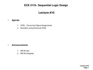
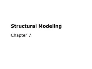
Lecture 17 VHDL Structural Modeling. Prith Banerjee ECE C03 Advanced Digital Design Spring 1998. Outline. Review of VHDL Structural VHDL Mixed Structural and Behavioral VHDL Use of hierarchy Combinational designs Component instantiation statements Concurrent statements

E N D
Lecture 17 VHDL Structural Modeling Prith Banerjee ECE C03 Advanced Digital Design Spring 1998 ECE C03 Lecture 17ECE C03 Lecture 6
Outline • Review of VHDL • Structural VHDL • Mixed Structural and Behavioral VHDL • Use of hierarchy • Combinational designs • Component instantiation statements • Concurrent statements • Process statements • Test Benches • READING: Dewey 12.1, 12.2, 12.3, 12.4, 13.1, 13.2, 13.3. 13.4, 13.6, 13.7. 13.8 ECE C03 Lecture 17ECE C03 Lecture 6
Review of VHDL • VHDL Includes facilities for describing the FUNCTION and STRUCTURE • At Various levels from abstract to the gate level • Intended as a modeling language for specification and simulation ECE C03 Lecture 17ECE C03 Lecture 6
Example of Behavioral Modeling(AND_OR_INVERT) or_gate: process (and_a, and_b) is begin or_a_b <= and_a or and_b; end process or_gate; inv : process (or_a_b) is begin y <= not or_a_b; end process inv; end architecture primitive; architecture primitive of and_or_inv is signal and_a, and_b, or_a_b : bit; begin and_gate_a : process (a1,a2) is begin and_a <= a1 and a2; end process and_gate_a; and_gate_b : process (b1,b2) is begin and_b <= b1 and b2; end process and_gate_b; a1 a2 y b1 b2 ECE C03 Lecture 17ECE C03 Lecture 6
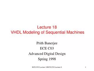
Behavioral Model of Computer System architecture abstract of computer is subtype word is bit_vector(31 downto 0); signal address: natural; signal read_data, write_data : word; signal mem_read, mem_write : bit := ‘0’; signal mem_ready : bit := ‘0’; cpu: process is begin -- described in next slide end process cpu; mem: process is begin -- described in next slide end process meml end architecture abstract; cpu Mem_ready Mem_read Mem_write mem ECE C03 Lecture 17ECE C03 Lecture 6
Model of Computer System (Contd) cpu: process is variable instr_reg, PC : word; begin loop address <= PC; mem_read <= ‘1’; wait until mem_ready = ‘1’; PC := PC + 4; -- variable assignment, not a signal; … --- execute instruction end loop; end process cpu; ECE C03 Lecture 17ECE C03 Lecture 6
Model of Computer System (Contd) memory: process is type memory_array is array (0 to 2**14 - 1) of word; variable store: memory_array := (…); begin wait until mem_read = ‘1’ or mem_write = ‘1’; if mem_read = ‘1’ then read_data <= store(address/4); mem_ready <= ‘1’; wait until mem_ready = ‘0’; else …. --- perform write access; end process memory; ECE C03 Lecture 17ECE C03 Lecture 6
Structural Descriptions • A structural description of a system is expressed in terms of subsystems interconnected by signals • Each subsystem may in turn be composed of of an interconnection of sub-subsystems • Component instantiation and port maps entity entity_name [ architecture_identifier] port map ( port_name => signal_name expression open, ); ECE C03 Lecture 17ECE C03 Lecture 6
Example of Component Instantiation entity DRAM_controller is port (rd, wr, mem: in bit; ras, cas, we, ready: out bit); end entity DRAM_controller; • We can then perform a component instantiation as follows assuming that there is a corresponding architecture called “fpld” for the entity. main_mem_cont : entity work.DRAM_controller(fpld) port map(rd=>cpu_rd, wr=>cpu_wr, mem=>cpu_mem, ready=> cpu_rdy, ras=>mem_ras, cas=>mem_cas, we=>mem_we); ECE C03 Lecture 17ECE C03 Lecture 6
Example of a four-bit register • Let us look at a 4-bit register built out of 4 D latches reg4 d0 d1 d2 d2 en clk q0 q2 q3 q4 ECE C03 Lecture 17ECE C03 Lecture 6
Behavioral Description of Register Architecture behavior of reg4 is begin storage : process is variable stored_d0, stored_d1, stored_d2, stored_d3: bit; begin if en = ‘1’ and clk = ‘1’ then stored_d0 := d0; -- variable assignment stored_d1 := d1; stored_d2 := d2; stored_d3 := d3; endif; q0 <= stored_d0 after 5 nsec; q1 <= stored_d1 after 5 nsec; q2 <= stored_d2 after 5 nsec; q3 <= stored_d3 after 5 nsec; wait on d0, d1, d2, d3; end process storage; and architecture behavior; ECE C03 Lecture 17ECE C03 Lecture 6
Structural Composition of Register d_latch d q d0 q0 clk d_latch d d1 q q1 clk d_latch d d2 q q2 clk d_latch d3 d and2 q q3 en a y clk clk b int_clk ECE C03 Lecture 17ECE C03 Lecture 6
Structural VHDL Description of Register entity d_latch is port(d, clk: in bit; q: out bit); end d_latch; architecture basic of d_latch is begin latch_behavior: process is begin if clk = ‘1’ then q <= d after 2 ns; end if; wait on clk, d; end process latch_behavior; end architecture basic; entity and2 is port (a, b: in bit; y: out bit); end and2; architecture basic of and2 is begin and2_behavior: process is begin y <= a and b after 2 ns; wait on a, b; end process and2_behavior; end architecture basic; ECE C03 Lecture 17ECE C03 Lecture 6
Structural VHDL Description of Register entity reg4 is port(d0, d1, d2, d3, en, clk: in bit; q0, q1, q2, q3: out bit); end entity reg4; architecture struct of reg4 is signal int_clk : bit; begin bit0: entity work.d_latch(basic) port map(d0, int_clk, q0); bit1: entity work.d_latch(basic) port map(d1, int_clk, q1); bit2: entity work.d_latch(basic) port map(d2, int_clk, q2); bit0: entity work.d_latch(basic) port map(d3, int_clk, q3); gate: entity work.and2(basic) port map(en, clk, int_clk); end architecture struct; ECE C03 Lecture 17ECE C03 Lecture 6
Mixed Structural and Behavioral Models • Models need not be purely structural or behavioral • Often it is useful to specify a model with some parts composed of interconnected component instances and other parts using processes • Use signals as a way to join component instances and processes • A signal can be associated with a port of a component instance and can be assigned to or read in a process ECE C03 Lecture 17ECE C03 Lecture 6
Example of Mixed Modeling: Multiplier architecture mixed of multiplier is signal partial_product, full_product: integer; signal arith_control, result_en, mult_bit, mult_load: bit; begin -- mized arith_unit: entity work.shift_adder(behavior) port map( addend => multiplicand, augend => full_product, sum => partial_product, add_control => arith_control); result : entity work,reg(behavior) port map (d => partial_product, q => full_product, en => result_en, reset => reset); multiplier_sr: entity work.shift_reg(behavior) port map (d => multiplier, q => mult_bit, load => mult_load, clk => clk); product <= full_product; control_section: process is begin -- sequential statements to assign values to control signals end process control_section; end architecture mixed; Entity multiplier is port(clk, reset: in bit; multiplicand, multiplier: in integer; product: out integer; end entity multiplier; Multiplier (register) multiplicand Arith_unit (shift adder) clk Result (shift register) ECE C03 Lecture 17ECE C03 Lecture 6
Component and Signal Declarations • The declarative part of the architecture STRUCTURE contains: • component declaration • signal declaration • Example of component declaration • component AND2_OP • port (A, B: in bit; Z : out bit); • end component; • Components and design entities are associated by signals, e.g. A_IN, B_IN • Signals are needed to interconnect components • signal INT1, INT2, INT3: bit; ECE C03 Lecture 17ECE C03 Lecture 6
Component Instantiation Statements • The statement part of an architecture body of a structural VHDL description contains component instantiation statements • FORMAT label : component_name port map (positional association of ports); label : component_name port map (named association of ports); • EXAMPLES A1: AND2_OP port map (A_IN, B_IN, INT1); A2: AND2_OP port map (A=>A_IN, C=>C_IN,Z=>INT2); ECE C03 Lecture 17ECE C03 Lecture 6
Hierarchical Structures • Can combine 2 MAJORITY functions (defined earlier) and AND gate to form another function entity MAJORITY_2X3 is port (A1, B1,C1,A2, B2, C2: in BIT; Z_OUT: out BIT); end MAJORITY_2X3; architecture STRUCTURE of MAJORITY_2X3 is component MAJORITY port (A_IN, B_IN, C_IN: in BIT; Z_OUT : out BIT); end component; component AND2_OP end component; signal INT1, INT2 : BIT; begin M1: MAJORITY port map (A1, B1, C1, INT1); M2: MAJORITY port map (A1, B2, C2, INT2); A1: AND2_OP port map (INT1, INT2, Z_OUT); end STRUCTURE; ECE C03 Lecture 17ECE C03 Lecture 6
Concurrent Signal Assignments entity XOR2_OP is port (A, B: in BIT; Z : out BIT); end entity; -- body architecture AND_OR of XOR2_OP is begin Z <= (not A and B) or (A and not B); end AND_OR; • The signal assignment Z <= .. Implies that the statement is executed whenever an associated signal changes value ECE C03 Lecture 17ECE C03 Lecture 6
Concurrent Signal Assignment entity XOR2_OP is port (A, B: in BIT; Z : out BIT); end entity; -- body architecture AND_OR_CONCURRENT of XOR2_OP is --signal declaration; signal INT1, INT2 : BIT; begin -- different order, same effect INT1 <= A and not B; -- INT1 <= A and not B; INT2 <= not A and B; -- Z <= INT1 or INT2; Z <= INT1 or INT2; -- INT2 <= not A and B; end AND_OR_CONCURRENT; • Above, the first two statements will be executed when A or B changes, and third if Z changes • Order of statements in the text does not matter ECE C03 Lecture 17ECE C03 Lecture 6
VHDL Modeling Styles • Structural representation describes system by specifying the interconnection of components that comprise a system • Behavioral representation in VHDL defines an input-output function • Procedural or algorithmic style uses sequential statements such as normal programming languages • top to bottom left to right order of statements • Nonprocedural or dataflow style uses concurrent signal assignment ECE C03 Lecture 17ECE C03 Lecture 6
Concurrent and Sequential Statements • VHDL provides both concurrent and sequential signal assignment statements • Example SIG_A <= IN_A and IN_B; SIG_B <= IN_A nor IN_C; SIG_C <= not IN_D; • The above sequence of statements can be concurrent or sequential depending on context • If above appears inside an architecture body, it is a concurrent signal assignment • If above appears inside a process statement, they will be executed sequentially ECE C03 Lecture 17ECE C03 Lecture 6
Data Flow Modeling of Combinational Logic • Consider a parity function of 8 inputs entity EVEN_PARITY is port (BVEC : in BIT_VECTOR(7 downto 0; PARITY: out BIT); end EVEN_PARITY; architecture DATA_FLOW of EVEN_PARITY is begin PARITY <= BVEC(0) xor BVEC(1) xor BVEC(2) xor BVEC(3) xor BVEC(4) xor BVEC(5) xor BVEC(6) xor BVEC(7) end DATA_FLOW; ECE C03 Lecture 17ECE C03 Lecture 6
Alternative Logic Implementations of PARITY TREE CONFIGURATION CASCADE CONFIGURATION ECE C03 Lecture 17ECE C03 Lecture 6
Suggestions of Hardware Implementation architecture TREE of EVEN_PARITY is signal INT1, INT2, INT3, INT4, INT5, INT6 : BIT; begin INT1 <= BVEC(0) xor BVEC(1) ; INT2 <= BVEC(2) xor BVEC(3) ; INT3 <= BVEC(4) xor BVEC(5) ; INT4 <= BVEC(6) xor BVEC(7); --second row of tree INT5 <= INT1 xor INT6; INT6 <= INT3 xor INT4; -third row of tree PARITY <= INT5 xor INT6; end DATA_FLOW; ECE C03 Lecture 17ECE C03 Lecture 6
Alternative Architecture Bodies • Three different VHDL descriptions of the even parity generator were shown • They have the same interface but three different implementation • Use the same entity description but different architecture bodies architecture DATA_FLOW of EVEN_PARITY is ... architecture TREE of EVEN_PARITY is ... architecture CASCADE of EVEN_PARITY is ... ECE C03 Lecture 17ECE C03 Lecture 6
VHDL Design of Cascaded Implementation architecture CASCADE of EVEN_PARITY is signal INT1, INT2, INT3, INT4, INT5, INT6 : BIT; begin INT1 <= BVEC(0) xor BVEC(1) ; INT2 <= INT1 xor BVEC(2); INT3 <= INT2 xor BVEC(3) ; INT4 <= INT3 xor BVEC(4); INT5 <= INT4 xor BVEC(5); INT6 <= INT5 xor BVEC(6); PARITY <= INT6 xor BVEC(7); end DATA_FLOW; ECE C03 Lecture 17ECE C03 Lecture 6
Bit Vectors • We now formally describe the bit vector type • BVEC: in BIT_VECTOR (7 downto 0); • BIT_VECTOR is an array type where each element of of type BIT; • Not e that BIT_VECTOR itself is not an array, it is a template for an array, i.e. a type • BVEC is array defined as a signal, variable or port • An array in VHDL has three characteristics • type of elements in the array (BIT) • length of the array (8) • indices of the array (7 to 0) BIT_VECTOR type . o o o o BVEC signal ECE C03 Lecture 17ECE C03 Lecture 6
Bit Vectors • Can specify in ascending or descending order • BVEC: BIT_VECTOR(0 to 7); • BVEC: BIT_VECTOR(8 to 15); • BVEC: BIT_VECTOR(15 downto 8); • Can specify values • SIG_A <= B”11100011”; • -- B is binary, O is octal, X is hex • Can define vector logic or shift operations • signal SIG_A, SIG_B, SIG_C: BIT_VECTOR(7 downto 0); • SIG_C <= SIG_A nor SIG_B; -- performs bitwise nor • B”1100” sla 1 = B”1000” -- shift left arithmetic by one • B”1100” ror 1 = B”0110” -- rotate right logical ECE C03 Lecture 17ECE C03 Lecture 6
Process Statements • FORMAT PROCESS_LABEL: process -- declarative part declares functions, procedures, types, constants, variables, etc begin -- Statement part sequential statement; sequential statement; wait statement; -- eg. Wait for 1 ms; or wait on ALARM_A; sequential statement; … wait statement; end process; Flow of control ECE C03 Lecture 17ECE C03 Lecture 6
Concurrent and Sequential Statements CONCURRENT: block begin COMM_BUS <= ‘1’; -- concurrent signal assignment DATA_BUS <= ‘0’; -- concurrent signal assignment end block CONCURRENT; SEQUENTIAL: process begin COMM_BUS <= ‘1’; -- sequential signal assignment DATA_BUS <= ‘0’; -- sequential signal assignment end process SEQUENTIAL; ECE C03 Lecture 17ECE C03 Lecture 6
Variable and Sequential Signal Assignment • Variable assignment • new values take effect immediately after execution variable LOGIC_A, LOGIC_B : BIT; LOGIC_A := ‘1’; LOGIC_B := LOGIC_A; • Signal assignment • new values take effect after some delay (delta if not specified) signal LOGIC_A : BIT; LOGIC_A <= ‘0’; LOGIC_A <= ‘0’ after 1 sec; LOGIC_A <= ‘0’ after 1 sec, ‘1’ after 3.5 sec; ECE C03 Lecture 17ECE C03 Lecture 6
Test Benches • One needs to test the VHDL model through simulation • We often test a VHDL model using an enclosing model called a test bench • A test bench consists of an architecture body containing an instance of the component to be tested • It also consists of processes that generate sequences of values on signals connected to the component instance ECE C03 Lecture 17ECE C03 Lecture 6
Example Test Bench Entity test_bench is end entity test_bench; architecture test_reg4 of test_bench is signal d0, d1, d2, d3, en, clk, q0, q1, q2, q3: bit; begin dut: entity work.reg4(behav) port map (d0, d1, d2, d3, d4, en, clk, q0, q1, q2, q3); stimulus: process is begin d0 <= ‘1’; d1 <= ‘1’; d2 <= ‘1’; d3 <= ‘1’; en <= ‘0’; clk <= ‘0’; wait for 20 ns; en <= ‘1’; wait for 20 ns; clk <= ‘1’; wait for 20 ns; d0 <= ‘0’; d1 <= ‘0’; d2 <= ‘0’; d3 <= ‘0’; wait for 20 ns; en <= ‘0’; wait for 20 ns; …. wait; end process stimulus; end architecture test_reg4; ECE C03 Lecture 17ECE C03 Lecture 6
Summary • Review of VHDL • Structural VHDL • Mixed Structural and behavioral VHDL • Use of Hierarchy • Component instantiation statements • Concurrent statements • Process statements • Test Benches • READING: Dewey 17.1, 17.3, 17.4, 17.5, 17.6, 17.7, 17.8, 17.10, 18.1, 18.2 ECE C03 Lecture 17ECE C03 Lecture 6