Wireless & Mobile Communication
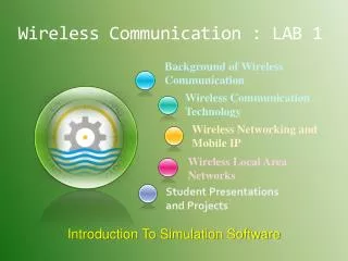
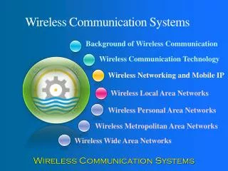
Wireless & Mobile Communication. Background of Wireless Communication. Wireless Communication Technology. Wireless Networking and Mobile IP. Wireless Local Area Networks. Student Presentations and Projects. Wireless Telecommunication Systems. Ch. 4: Wireless Telecommunication Systems.

Wireless & Mobile Communication
E N D
Presentation Transcript
Wireless & Mobile Communication Background of Wireless Communication Wireless Communication Technology Wireless Networking and Mobile IP Wireless Local Area Networks Student Presentations and Projects Wireless Telecommunication Systems
Ch. 4: Wireless Telecommunication Systems Market GSM DECT TETRA UMTS/IMT-2000
Data services in GSM I • Data transmission standardized with only 9.6 kbit/s • advanced coding allows 14.4 kbit/s • not enough for Internet and multimedia applications • HSCSD (High-Speed Circuit Switched Data) • mainly software update • bundling of several time-slots to get higher AIUR (Air Interface User Rate, e.g., 57.6 kbit/s using 4 slots @ 14.4) • advantage: ready to use, constant quality, simple • disadvantage: channels blocked for voice transmission
Data services in GSM II • GPRS (General Packet Radio Service) • packet switching • using free slots only if data packets ready to send (e.g., 50 kbit/s using 4 slots temporarily) • standardization 1998, introduction 2001 • advantage: one step towards UMTS, more flexible • disadvantage: more investment needed (new hardware) • GPRS network elements • GSN (GPRS Support Nodes): GGSN and SGSN • GGSN (Gateway GSN) • interworking unit between GPRS and PDN (Packet Data Network) • SGSN (Serving GSN) • supports the MS (location, billing, security) • GR (GPRS Register) • user addresses
GPRS architecture and interfaces SGSN Gn PDN MS BSS SGSN GGSN Um Gb Gn Gi HLR/ GR MSC VLR EIR
GPRS protocol architecture MS BSS SGSN GGSN Um Gb Gn Gi apps. IP/X.25 IP/X.25 SNDCP SNDCP GTP GTP LLC LLC UDP/TCP UDP/TCP RLC RLC BSSGP BSSGP IP IP MAC MAC FR FR L1/L2 L1/L2 radio radio
DECT • DECT (Digital European Cordless Telephone) standardized by ETSI (ETS 300.175-x) for cordless telephones • standard describes air interface between base-station and mobile phone • DECT has been renamed for international marketing reasons into „Digital Enhanced Cordless Telecommunication“ • Characteristics • frequency: 1880-1990 MHz • channels: 120 full duplex • duplex mechanism: TDD (Time Division Duplex) with 10 ms frame length • multplexing scheme: FDMA with 10 carrier frequencies, TDMA with 2x 12 slots • modulation: digital, Gaußian Minimum Shift Key (GMSK) • power: 10 mW average (max. 250 mW) • range: approx. 50 m in buildings, 300 m open space
DECT system architecture reference model D4 D3 VDB D2 PA PT FT local network HDB PA PT D1 global network FT local network
DECT reference model • close to the OSI reference model • management plane over all layers • several services in C(ontrol)- and U(ser)-plane C-Plane U-Plane signaling, interworking application processes network layer OSI layer 3 management data link control data link control OSI layer 2 medium access control physical layer OSI layer 1
DECT layers I • Physical layer • modulation/demodulation • generation of the physical channel structure with a guaranteed throughput • controlling of radio transmission • channel assignment on request of the MAC layer • detection of incoming signals • sender/receiver synchronization • collecting status information for the management plane • MAC layer • maintaining basic services, activating/deactivating physical channels • multiplexing of logical channels • e.g., C: signaling, I: user data, P: paging, Q: broadcast • segmentation/reassembly • error control/error correction
DECT layers II • Data link control layer • creation and keeping up reliable connections between the mobile terminal and base station • two DLC protocols for the control plane (C-Plane) • connectionless broadcast service:paging functionality • Lc+LAPC protocol:in-call signaling (similar to LAPD within ISDN), adapted to the underlying MAC service • several services specified for the user plane (U-Plane) • null-service: offers unmodified MAC services • frame relay: simple packet transmission • frame switching: time-bounded packet transmission • error correcting transmission: uses FEC, for delay critical, time-bounded services • bandwidth adaptive transmission • “Escape” service: for further enhancements of the standard
DECT layers III • Network layer • similar to ISDN (Q.931) and GSM (04.08) • offers services to request, check, reserve, control, and release resources at the basestation and mobile terminal • resources • necessary for a wireless connection • necessary for the connection of the DECT system to the fixed network • main tasks • call control: setup, release, negotiation, control • call independent services: call forwarding, accounting, call redirecting • mobility management: identity management, authentication, management of the location register
Enhancements of the standard DECT basestation DECT Common Air Interface DECT Portable Part fixed network GAP • Several „DECT Application Profiles“ in addition to the DECT specification • GAP (Generic Access Profile) standardized by ETSI in 1997 • assures interoperability between DECT equipment of different manufacturers (minimal requirements for voice communication) • enhanced management capabilities through the fixed network: Cordless Terminal Mobility (CTM) • DECT/GSM Interworking Profile (GIP): connection to GSM • ISDN Interworking Profiles (IAP, IIP): connection to ISDN • Radio Local Loop Access Profile (RAP): public telephone service • CTM Access Profile (CAP): support for user mobility
TETRA - Terrestrial Trunked Radio • Trunked radio systems • many different radio carriers • assign single carrier for a short period to one user/group of users • taxi service, fleet management, rescue teams • interfaces to public networks, voice and data services • very reliable, fast call setup, local operation • TETRA - ETSI standard • formerly: Trans European Trunked Radio • point-to-point and point-to-multipoint • encryption (end-to-end, air interface), authentication of devices, users and networks • group call, broadcast, sub-second group-call setup • ad-hoc (“direct mode”), relay and infrastructure networks • call queuing with pre-emptive priorities
TETRA – Contracts by Sector (percentage) Used in over 70 countries, more than 20 device manufacturers
TETRA – Network Architecture TETRA infrastructure PSTN, ISDN, Internet, PDN switch NMS switch switch BS ISI other TETRA networks BS AI BS AI: Air Interface BS: Base Station DMO: Direct Mode Operation ISI: Inter-System Interface NMS: Network Management System PEI: Peripheral Equipment Interface DMO PEI
TETRA – Direct Mode I • Direct Mode enables ad-hoc operation and is one of the most important differences to pure infrastructure-based networks such as GSM, cdma2000 or UMTS. network “Dual Watch” – alternating participation in Infrastructure and ad-hoc Individual Call network Authorizing mobile station Group Call Managed Direct Mode
TETRA – Direct Mode II • An additional repeater may increase the transmission range (e.g. police car) network Direct Mode with Repeater Direct Mode with Gateway network network Authorizing Repeater Managed Repeater/Gateway Direct Mode with Repeater/Gateway
TETRA – Technology • Services • Voice+Data (V+D) and Packet Data Optimized (PDO) • Short data service (SDS) • Frequencies • Duplex: FDD, Modulation: DQPSK • Europe (in MHz, not all available yet) • 380-390 UL / 390-400 DL; 410-420 UL / 420-430 DL, 450-460 UL / 460-470 DL; 870-876 UL / 915-921 DL • Other countries • 380-390 UL / 390-400 DL; 410-420 UL / 420-430 DL, 806-821 UL / 851-866 DL
TETRA – Data Rates • Infrastructure mode, V+D in kbit/s • No. of time slots 1 2 3 4 • No protection 7.2 14.4 21.6 28.8 • Low protection 4.8 9.6 14.4 19.2 • High protection 2.4 4.8 7.2 9.6 • TETRA Release 2 – Supporting higher data rates • TEDS (TETRA Enhanced Data Service) • up to 100 kbit/s • backward compatibility
UMTS and IMT-2000 • Proposals for IMT-2000 (International Mobile Telecommunications) • UWC-136, cdma2000, WP-CDMA • UMTS (Universal Mobile Telecommunications System) from ETSI • UMTS • UTRA (was: UMTS, now: Universal Terrestrial Radio Access) • enhancements of GSM • EDGE (Enhanced Data rates for GSM Evolution): GSM up to 384 kbit/s • CAMEL (Customized Application for Mobile Enhanced Logic) • VHE (virtual Home Environment) • fits into GMM (Global Multimedia Mobility) initiative from ETSI • requirements • min. 144 kbit/s rural (goal: 384 kbit/s) • min. 384 kbit/s suburban (goal: 512 kbit/s) • up to 2 Mbit/s urban
Frequencies for IMT-2000 1850 1900 1950 2000 2050 2100 2150 2200 MHz ITU allocation (WRC 1992) IMT-2000 MSS IMT-2000 MSS GSM 1800 DE CT T D D UTRA FDD MSS T D D UTRA FDD MSS Europe GSM 1800 IMT-2000 MSS IMT-2000 MSS China PHS cdma2000 W-CDMA MSS cdma2000 W-CDMA MSS Japan PCS MSS rsv. MSS North America MHz 1850 1900 1950 2000 2050 2100 2150 2200
IMT-2000 family Flexible assignment of Core Network and Radio Access Interface for Internetworking IMT-2000 Core Network ITU-T GSM (MAP) ANSI-41 (IS-634) IP-Network Initial UMTS (R99 w/ FDD) IMT-DS (Direct Spread) UTRA FDD (W-CDMA) 3GPP IMT-TC (Time Code) UTRA TDD (TD-CDMA); TD-SCDMA 3GPP IMT-MC (Multi Carrier) cdma2000 3GPP2 IMT-SC (Single Carrier) UWC-136 (EDGE) UWCC/3GPP IMT-FT (Freq. Time) DECT ETSI IMT-2000 Radio Access ITU-R
UMTS architecture(Release 99 used here!) • UTRAN (UTRA Network) • Cell level mobility • Radio Network Subsystem (RNS) • Encapsulation of all radio specific tasks • UE (User Equipment) • CN (Core Network) • Inter system handover • Location management if there is no dedicated connection between UE and UTRAN Uu Iu UE UTRAN CN
UMTS domains and interfaces I • User Equipment Domain • Assigned to a single user in order to access UMTS services • Infrastructure Domain • Shared among all users • Offers UMTS services to all accepted users Home Network Domain Zu Cu Uu Iu Yu USIM Domain MobileEquipment Domain Access Network Domain Serving Network Domain Transit Network Domain Core Network Domain User Equipment Domain Infrastructure Domain
UTRAN architecture RNC: Radio Network Controller RNS: Radio Network Subsystem RNS UE1 Iub Node B Iu RNC CN UE2 Node B Node B • UTRAN comprises several RNSs • Node B can support FDD or TDD or both • RNC is responsible for handover decisions requiring signaling to the UE • Cell offers FDD or TDD UE3 Iur Node B Iub Node B RNC Node B Node B RNS
UTRAN functions • Admission control • Congestion control • System information broadcasting • Radio channel encryption • Handover • SRNS moving • Radio network configuration • Channel quality measurements • Macro diversity • Radio carrier control • Radio resource control • Data transmission over the radio interface • Outer loop power control (FDD and TDD) • Channel coding • Access control
Core network: protocols PSTN/ ISDN PDN (X.25), Internet (IP) VLR MSC GMSC GSM-CS backbone RNS HLR RNS SGSN GGSN Layer 3: IP GPRS backbone (IP) Layer 2: ATM SS 7 Layer 1: PDH, SDH, SONET UTRAN CN
Core network: architecture VLR BSS Abis BTS Iu BSC MSC GMSC PSTN Node B BTS IuCS AuC EIR HLR GR Node B Iub Node B RNC SGSN GGSN Gi Gn Node B Node B IuPS CN RNS
Core network • The Core Network (CN) and thus the Interface Iu, too, are separated into two logical domains: • Circuit Switched Domain (CSD) • Circuit switched service incl. signaling • Resource reservation at connection setup • GSM components (MSC, GMSC, VLR) • IuCS • Packet Switched Domain (PSD) • GPRS components (SGSN, GGSN) • IuPS • Release 99 uses the GSM/GPRS network and adds a new radio access! • Helps to save a lot of money … • Much faster deployment • Not as flexible as newer releases (5, 6)
Example handover types in UMTS/GSM UE1 Node B1 RNC1 3G MSC1 Iu UE2 Node B2 Iur Iub UE3 Node B3 RNC2 3G MSC2 UE4 BTS BSC 2G MSC3 Abis A
UMTS services (originally) Service Profile Bandwidth Transport mode High Interactive MM 128 kbit/s Circuit switched Bidirectional, video telephone High MM 2 Mbit/s Packet switched Low coverage, max. 6 km/h Medium MM 384 kbit/s Circuit switched asymmetrical, MM, downloads Switched Data 14.4 kbit/s Circuit switched Simple Messaging 14.4 kbit/s Packet switched SMS successor, E-Mail Voice 16 kbit/s Circuit switched • Data transmission service profiles • Virtual Home Environment (VHE) • Enables access to personalized data independent of location, access network, and device • Network operators may offer new services without changing the network • Service providers may offer services based on components which allow the automatic adaptation to new networks and devices • Integration of existing IN services
Example 3G Networks: Japan FOMA (Freedom Of Mobile multimedia Access) in Japan Examples for FOMA phones
Example 3G networks: Australia cdma2000 1xEV-DO in Melbourne/Australia Examples for 1xEV-DO devices
UMTS in Europe Orange/UK Vodafone/Germany
Q&A ?