Download
1 / 43
430 likes | 503 Views
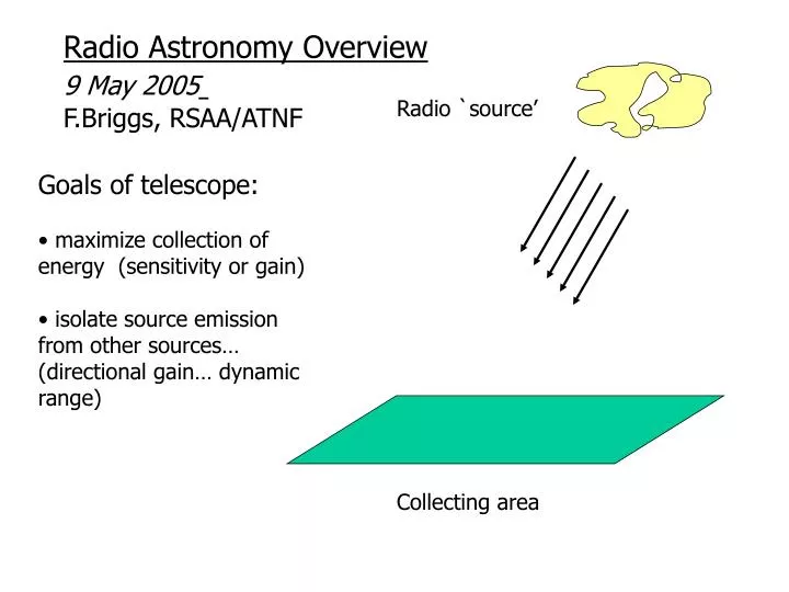
Radio Astronomy Overview 9 May 2005 F.Briggs, RSAA/ATNF. Radio `source’. Goals of telescope: maximize collection of energy (sensitivity or gain) isolate source emission from other sources… (directional gain… dynamic range). Collecting area. Login: obstech passwd: [see me or Peter].

E N D
Radio Astronomy Overview 9 May 2005 F.Briggs, RSAA/ATNF Radio `source’ • Goals of telescope: • maximize collection of energy (sensitivity or gain) • isolate source emission from other sources… (directional gain… dynamic range) Collecting area
* *** (biblical status in field)
More references: • Synthesis Imaging in Radio Astronomy, 1998, ASP Conf. Series, Vol 180, eds. Taylor, Carilli & Perley • Single-Dish Radio Astronomy, 2002, ASP Conf. Series, Vol 278, eds. Stanimirovic, Altschuler, Goldsmith & Salter • AIPS Cookbook, http://www.aoc.nrao.edu/aips/
LOFAR + MWA-LFD VLA ALMA GMRT ground based radio techniques 350m 10 MHz ATCA
Parkes “The Dish”
VLA, Very Large Array New Mexico
300 metres Arecibo Telescope… in Puerto Rico
91 metres GBT Green Bank West Virginia … the newest… … and last (perhaps)… … big dish Unblocked Aperture
Atacama L Millimeter Array Very Large Array USA Westerbork Telescope Netherlands
VLBA Very Long Baseline Array for: Very Long Baseline Interferometry
LBA: Long Baseline Array in AU EVN: European VLBI Network(more and bigger dishes than VLBA)
1) Thermal 2) Non-Thermal Radio “Sources” Spectra: • Thermal • emission mechanism related • to Planck BB… electrons have • ~Maxwellian distribution • 2) Non-Thermal • emission typically from • relativistic electrons in • magnetic field… electrons • have ~power law energy • distribution Flux Density Distinctive Radio Spectra ! Frequency MHz
Thermal M81 Group of Galaxies Visible Light Radio map of cold hydrogen gas
Inwhere In~ Sn/W can assign “brightness temperature” to objects where “Temp” really has no meaning…
Brightest Sources in Sky Flux Density [Jansky] Frequency MHz (from Kraus, Radio Astronomy)
Radio `source’ • Goals of telescope: • maximize collection of energy (sensitivity or gain) • isolate source emission from other sources… (directional gain… dynamic range) Collecting area
Incident waves Radio telescopes are Diffraction Limited
Incident waves Radio telescopes are Diffraction Limited Waves arriving from slightly different direction have q Phase gradient across aperture… When l/2, get cancellation: Resolution = q ~ l/D
Actually……. Noise …. time series Time Fourier transform Frequency
F.T. of noise time series Frequency Narrow band filter B Hz Frequency Envelope of time series varies on scale t ~ 1/B sec Time
thought experiment… Cartoon antenna 2 wires out (antennas are “reciprocal” devices… can receive or broadcast)
thought experiment… Black Body oven at temperature = T
Black Body oven at temperature = T thought experiment… R
Black Body oven at temperature = T thought experiment… … wait a while… reach equilibrium… at T R warm resistor delivers power P = kT B (B = frequency bandwidth; k = Boltzmann Const)
R real definition… Measure Antenna output Power as “Ta” = antenna temperature Ta temp = T warm resistor produces P = kT B = Pa = kTa B
Q Radio `source’ Reception Pattern or Power Pattern Collecting area
Radio `source’ If source with brightness temperature Tb fills the beam (reception pattern), then Ta = Tb Collecting area (!! No dependence on telescope if emission fills beam !!)
receiver “temperature”… quantify Receiver internal noise Power as “Tr” = “receiver temperature” Ta Ampl, etc Real electronics adds noise …treat as ideal, noise-free amp with added power from warm R Tr+Ta Ampl, etc
“system temperature”… quantify total receiver System noise power as “Tsys” [include spillover, scattering, etc] Tsys+Ta Ampl, etc RMS fluctuations = DT DT = (fac)Tsys/(B tint)1/2 Fac ~ 1 – 2 B = Bandwidth, Hz tint = integration time, seconds
Radio `point source’ Power collected = SnAeff B/2 Sn = flux density (watts/sq-m/Hz) [ 1 Jansky = 1 Jy = 10-26 w/sq-m/Hz ] Aeff = effective area (sq-m) B = frequency bandwith (Hz) Ta = SnAeff /2k Collecting area
“Resolved” “Unresolved” Sn = flux density Aeff = effective area (sq-m) Ta = SnAeff /2k If source fills the beam Ta = Tb RMS = DT = (fac)Tsys/(B tint)1/2 fac ~ 1 – 2 B = Bandwidth tint = integration time
High Velocity HI Cloud: NHI = 1 x 1019 cm-2 Example 1 NHI = 1.8 x 10¹⁸ Tb DVkm/s = 1.8 x 10¹⁸ Tb (10) Tb = 0.6 K 5 rms = 5DT = Tb= 0.6 K rms = DT = (fac)Tsys/(B tint)1/2 = (1)(30)/(B tint)1/2 tint= (30/0.12)2/(50x103) = 1.2 seconds B = (10/3x105)x1420x106 = 50 KHz (To reach NHI = 1 x 1017 cm-2 need 10,000 times longer ~ 3 hours)
Example 2 High redshift quasar with continuum flux density Sn = 100 mJy (Ta = SnAeff /2k) Ka = Ta / Sn = Aeff /2k [K/Jy] = 0.7 K/JyParkes = 10 K/JyArecibo = 2.7 K/Jy VLA = 300 K/Jy SKA Parkes: 100 mJy yields Ta = 70 mK 64 MHz continuum bandwidth for receiver 5 rms = 5DT = Tb= 0.07 K rms = DT = (fac)Tsys/(B tint)1/2 = (1)(30)/(B tint)1/2 tint= (30/0.014)2/(64x106) ~0.1 sec
Example 3: Array High redshift quasar with continuum flux density Sn = 1 mJy (Ta = SnAeff /2k) Ka = Ta / Sn = Aeff /2k [K/Jy] = 0.7 K/JyParkes = 6 x 0.1 = 0.6 K/JyACTA rms = DS = (fac)(Tsys /Ka)/(B tint)1/2 ATCA (B=128 MHz): 1 mJy = 5 rmsmeans DS= 0.2 mJy rms = DS = (fac)(Tsys /Ka)/(B tint)1/2 = (1.4)(30/0.6)/(B tint)1/2 tint= (70/0.0002)2/(128x106) ~16 min