Download
1 / 38
460 likes | 1.4k Views
INDUCTION MOTOR steady-state model. SEE 3433 MESIN ELEKTRIK. a. 120 o. 120 o. c’. b’. c. b. a’. 120 o. Stator windings of practical machines are distributed . Construction . Coil sides span can be less than 180 o – short-pitch or fractional-pitch or chorded winding.

E N D
INDUCTION MOTORsteady-state model SEE 3433 MESIN ELEKTRIK
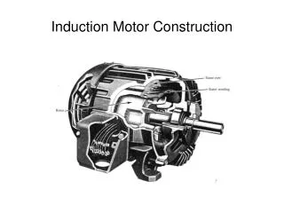
a 120o 120o c’ b’ c b a’ 120o Stator windings of practical machines are distributed Construction Coil sides span can be less than 180o – short-pitch or fractional-pitch or chorded winding If rotor is wound, its winding the same as stator Stator – 3-phase winding Rotor – squirrel cage / wound
Ni / 2 - /2 -/2 -Ni / 2 Single N turn coil carrying current i Spans 180o elec Permeability of iron >> o → all MMF drop appear in airgap a Construction a’
(3Nci)/2 (Nci)/2 -/2 - /2 Distributed winding – coils are distributed in several slots Nc for each slot Construction MMF closer to sinusoidal - less harmonic contents
The harmonics in the mmf can be further reduced by increasing the number of slots: e.g. winding of a phase are placed in 12 slots: Construction
In order to obtain a truly sinusoidal mmf in the airgap: Construction • the number of slots has to infinitely large • conductors in slots are sinusoidally distributed In practice, the number of slots are limited & it is a lot easier to place the same number of conductors in a slot
Phase a – sinusoidal distributed winding Air–gap mmf F() 2
i(t) t F() • Sinusoidal current excitation (with frequency s) in a phase produces space sinusoidal standing wave MMF • Sinusoidal winding for each phase produces space sinusoidal MMF and flux This is the excitation current which is sinusoidal with time
i(t) t F() • Sinusoidal current excitation (with frequency s) in a phase produces space sinusoidal standing wave MMF • Sinusoidal winding for each phase produces space sinusoidal MMF and flux 0 t = 0
Sinusoidal current excitation (with frequency s) in a phase produces space sinusoidal standing wave MMF • Sinusoidal winding for each phase produces space sinusoidal MMF and flux i(t) t t1 F() t = t1 2
Sinusoidal current excitation (with frequency s) in a phase produces space sinusoidal standing wave MMF • Sinusoidal winding for each phase produces space sinusoidal MMF and flux i(t) t t2 F() t = t2 2
Sinusoidal current excitation (with frequency s) in a phase produces space sinusoidal standing wave MMF • Sinusoidal winding for each phase produces space sinusoidal MMF and flux i(t) t t3 F() t = t3 2
Sinusoidal current excitation (with frequency s) in a phase produces space sinusoidal standing wave MMF • Sinusoidal winding for each phase produces space sinusoidal MMF and flux i(t) t t4 F() t = t4 2
Sinusoidal current excitation (with frequency s) in a phase produces space sinusoidal standing wave MMF • Sinusoidal winding for each phase produces space sinusoidal MMF and flux i(t) t t5 F() t = t5 2
Sinusoidal current excitation (with frequency s) in a phase produces space sinusoidal standing wave MMF • Sinusoidal winding for each phase produces space sinusoidal MMF and flux i(t) t t6 F() t = t6 2
Sinusoidal current excitation (with frequency s) in a phase produces space sinusoidal standing wave MMF • Sinusoidal winding for each phase produces space sinusoidal MMF and flux i(t) t t7 F() t = t7 2
Sinusoidal current excitation (with frequency s) in a phase produces space sinusoidal standing wave MMF • Sinusoidal winding for each phase produces space sinusoidal MMF and flux i(t) t t8 F() t = t8 2
Combination of 3 standing waves resulted in ROTATING MMF wave
Frequency of rotation is given by: p – number of poles f – supply frequency known as synchronous frequency
Emf in stator winding (known as back emf) Emf in rotor winding Rotor flux rotating at synchronous frequency • Rotating flux induced: Rotor current interact with flux to produce torque Rotor ALWAYS rotate at frequency less than synchronous, i.e. at slip speed:sl = s – r Ratio between slip speed and synchronous speed known as slip
Flux per pole: = 2 Bmaxl r Induced voltage Flux density distribution in airgap: Bmaxcos Sinusoidally distributed flux rotates at s and induced voltage in the phase coils Maximum flux links phase a when t = 0. No flux links phase a when t = 90o
Induced voltage a flux linkage of phase a a = N p cos(t) By Faraday’s law, induced voltage in a phase coil aa’ is Maximum flux links phase a when t = 0. No flux links phase a when t = 90o
Induced voltage In actual machine with distributed and short-pitch windinds induced voltage is LESS than this by a winding factor Kw
Stator phase voltage equation: Vs = Rs Is + j(2f)LlsIs + Eag Eag – airgap voltage or back emf (Erms derive previously) Eag = k f ag Rotor phase voltage equation: Er = Rr Ir + js(2f)Llr Er – induced emf in rotor circuit Er /s = (Rr / s) Ir + j(2f)Llr
Per–phase equivalent circuit Llr Ir Lls Rs + Vs – + Eag – + Er/s – Is Rr/s Lm Im Rs – stator winding resistance Rr – rotor winding resistance Lls – stator leakage inductance Llr – rotor leakage inductance Lm – mutual inductance s – slip
We know Eg and Er related by Where a is the winding turn ratio = N1/N2 The rotor parameters referred to stator are: • rotor voltage equation becomes • Eag = (Rr’ / s) Ir’ + j(2f)Llr’ Ir’
Is Lls Llr’ Ir’ Rs + Eag – + Vs – Rr’/s Lm Im Per–phase equivalent circuit Rs – stator winding resistance Rr’ – rotor winding resistance referred to stator Lls – stator leakage inductance Llr’ – rotor leakage inductance referred to stator Lm – mutual inductance Ir’ – rotor current referred to stator
Power and Torque Power is transferred from stator to rotor via air–gap, known as airgap power Lost in rotor winding Converted to mechanical power = (1–s)Pag= Pm
Power and Torque Mechanical power,Pm = Temr But, ss = s - r r = (1-s)s Pag = Tems Therefore torque is given by:
Power and Torque This torque expression is derived based on approximate equivalent circuit A more accurate method is to use Thevenin equivalent circuit:
Power and Torque Tem Pull out Torque (Tmax) Trated r 0 ratedsyn sTm s 1 0
Is Lls Llr’ Ir’ Rs + Eag – + Vs – Rr’/s Lm Im Steady state performance The steady state performance can be calculated from equivalent circuit, e.g. using Matlab
Is Lls Llr’ Ir’ Rs + Eag – + Vs – Rr’/s Lm Im Steady state performance e.g. 3–phase squirrel cage IM V = 460 V Rs= 0.25 Rr=0.2 Lr = Ls = 0.5/(2*pi*50) Lm=30/(2*pi*50) f = 50Hz p = 4