Download
1 / 14
140 likes | 257 Views
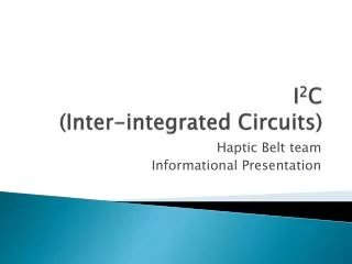
I 2 C investigations. - some reported problems from some APV users - sensitivity to “termination” resistance and power supply levels I 2 C scheme very simple, ought to be problem free - so what’s going on? Outline probable cause of problems

E N D
I2C investigations • - some reported problems from some APV users • - sensitivity to “termination” resistance • and power supply levels • I2C scheme very simple, ought to be problem free • - so what’s going on? • Outline • probable cause of problems • measurements on I2C transactions on CCUM/hybrid • measurements of APV I2C drive strength • possible solutions content here summarises e-mail exchanges between: S.Marchioro, R.Hammarstron, V.Commichau, J.Mnich, J-D.Berst, U.Goerlach, G.Hall, M.French, C.Ljuslin, C.Paillard, W.Karpinski. I2C website http://www.semiconductors.philips.com/i2c/ Mark Raymond m.raymond@ic.ac.uk CMS Tracker Electronics
I2C electrical scheme DRIVER (master, e.g. CCU) LEVEL SHIFTER APV (slave) I2C line (SDA) hysteresis Pull-up resistor 2.5V R 5V in in out C (parasitic) out DRIVER 0.25 mm CCU directly in CMS. VI2C in lab. CCU module for hybrid presently. LEVEL SHIFTER Not needed in CMS. Incorporated in CCUM. Various solutions possible. I2C line RC should be small cf I2C clock period (10ms). C will be layout dependent. APV (MUXPLL) hysteresis characteristic gives noise immunity input has to be pulled below lower threshold for APV to correctly recognise data What’s going wrong? Suspect problem arises due to output drive capability of level shifter stages combined with small values of pull-up resistor R. CMS Tracker Electronics
Level shifter circuits Opto-isolated level shifter (simplified schematic) used in APV test setup in IC lab isolation barrier 5V side 2.5V side Rpullup * DRIVER SDA Rpullup * APV SDA * Diodes used to implement bi-directionality use low forward drop devices (Schottky) but still ~ 0.25V or more if Rpullup small If SDA not pulled low enough to trip APV I/P hysteresis threshold then APV will fail to recognise its own address and I2C transaction will fail CCU module/hybrid system 5V 2.5V SDA APV side SDA CCU side Level shifting is implemented using MOSFET on CCU module Copes better with low values of Rpullup, but ON resistance still exists CMS Tracker Electronics
I2C measurements on the IC APV test setup 0 indicates write cycle APV address 0100001 0.25V APV acknowledges own address 0.35V APV fails to decode own address and so doesn’t generate acknowledge >0.35V I2C transaction fails on this setup if SDA line not pulled lower than ~ 0.35 Volts CMS Tracker Electronics
Measurements on the CCU module/hybrid setup ‘0’ indicates write cycle APV acknowledges own address APV address 0100001 0.25V 0.35V APV fails to decode own address and so doesn’t generate acknowledge >0.35V I2C transaction fails at pull-down voltage > ~ 0.35V corresponding to pull-up resistance of 375W = 1.5k // 500W (1.5k is built in resistance on CCU module) CMS Tracker Electronics
APV25 I2C drive strength How low can APV pull SDA line for a given pull-up resistor value? Use strong driver circuit (so that APV can always respond to I2C transaction) and use different values of Rpullup, measuring how low APV can pull SDA during Acknowledge cycle. address bit APV ACK bit write bit Vdiff e.g. for Rpullup = 500W APV can pull SDA line down to within 200mV of VSS (0V) CMS Tracker Electronics
Pull-up resistor/s (where and what value?) ? ? CCUM FEH ? OH Seems as though ought to be trivial, but of course isn’t quite In final system 0.25um CCU master talks directly to 0.25um APV/MUXPLL/LD slaves no level shifting required => problems go away Interim situation present CCUM, test systems incorporate level shifting stages will want to test hybrids (FEH,OH) in isolation, and together, on different test beds e.g. assume worst case cable capacitance ~100pF (reasonable?) for RC < 1ms (CR < 5t, t=5msec) => R ~ 10k Could split 10k between FEH and OH (20k on each) May need different variants depending on location in detector 5 ms SCK SDA C~cable capacitance R=pull-up resistor CMS Tracker Electronics
Pull-up resistor (where and what value?) Alternatively CCUM FEH OH Put pull-up here only (~few kW) Leave these resistors out altogether (or make large) Shouldn’t confuse pull-up with termination Present choice of resistor on CCUM (1.5k) will probably work in all cases Components on FEH and OH can be finalised now Suggestion only – others will want to comment CMS Tracker Electronics
Conclusions I2C problems experienced probably due to level shifter circuits coupled with low values of pull-up resistor Should be no problems in all 0.25mm final system Suggested solution put large pull-up resistor values on FEH and OH (~20k say) (will, in any case, be dominated by 1.5k on present CCUM) if necessary (large bus capacitance) put smaller value on CCUM CMS Tracker Electronics
Other matters APV25s1 biasing - manual needs update, I2C values correct for APV25s0, not s1 Recommended bias settings. Because of current mirroring change between s0 and s1 versions the numbers in the manual must change (approx 70% of s0 values). External bias at 128 mA, power supplies = 0, 1.25V, 2.5V IPRE 85 IPCASC 45 IPSF 30 ISHA ~30 (tune for optimum pulse rise time) ISSF 30 IPSP 48 IMUXIN 30 VFP ~30 (preamp fall time - can be higher but depends on occupancy) VFS ~60 (tune for optimum pulse fall time) Pulse shape tuning (rough guide): As detector capacitance increases ISHA needs to increase VFS needs to be reduced For capacitances in the range 0 -> 20 pF: ISHA in range 20 -> 65, VFS in range 65 -> 50 CMS Tracker Electronics
APV25s1 biasing Internal biasing dependence on value of on-chip resistor testing so far => 15 % increase of all I2C current settings (w.r.t. external (128mA) values) i.e. external (128mA) internal IPRE 85 98 IPCASC 45 52 IPSF 30 34 ISHA ~30 ~34 ISSF 30 34 IPSP 48 55 IMUXIN 30 34 => values in “internal” column should be used for the hybrid (for now) Need to find a strategy for choosing I2C bias current settings InternalIrefwill depend on local power supply values, and on internal resistor value (+/-10%) Can probably be managed by correction factor applied to all values (as above) to achieve “correct” power consumption Something to look at in system test? CMS Tracker Electronics
APV25s1 biasing • ICAL I2C register setting • determines magnitude of calibration step applied to capacitors • feeding preamp inputs • actual value of charge injected will depend on: • reference current value (external/internal(on-chip resistor value)) • I/V resistor value in bias generator • very small charge injection capacitors • can be used to calibrate (tune) pulse shape, but not for accurate gain measurement • rough value to get 1 mip signal • APV25s0 APV25s1 APV25s1 • external, 128mA external, 128mA internal • ~ 40 ~ 25 ~ 29 CMS Tracker Electronics
APV performance dependence on LV power supplies Currently under study, no show-stopping discoveries, but some aspects of performance affected (mainly dynamic range identified so far) Pictures show peak mode pulse shapes for signals from -2 to +6 mips in 0.5 mip steps gain change minimal but loss of headroom in –10% case assumptions so far: 2.7 V not exceeded power differences symmetrical on both rails I2C current settings tuned to get same analogue current for different PSU voltages CMS Tracker Electronics
APV performance dependence on LV power supplies CMS Tracker Electronics